



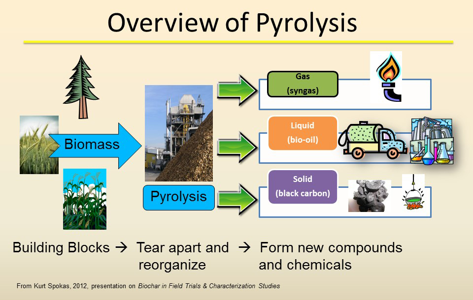
Biochar producers often concentrate on the carbon content and stability of the finished solid while giving less attention to the gases leaving the reactor. If combustible gas escapes, air enters the system or the oxidation stage performs poorly, a facility can lose energy, create safety risks and weaken its claimed climate benefit. Gas monitoring provides the missing connection between feedstock conversion, energy recovery and atmospheric release.
Biochar pyrolysis systems should generally monitor methane, carbon monoxide, carbon dioxide, hydrogen and oxygen at locations selected for process control, fuel utilisation and emissions assessment. Additional components should be chosen according to the feedstock, reactor design, gas-cleaning system, end use and applicable permit or certification method.
One instrument and one sampling point rarely answer every question. The hot gas leaving the reactor, the cleaned fuel stream and the final exhaust have different concentrations, contaminants and measurement objectives, so they should be evaluated separately.
Why Has Methane Monitoring Become More Important for Biochar Projects?
A project may store carbon in biochar while releasing avoidable methane during production. Because methane affects the net climate result, overlooking it can reduce the credibility of the project even when the solid product meets its quality targets.
The 2026 EU methodology for voluntary certification of biochar carbon removal includes production-related greenhouse gases in the calculation of associated emissions. It identifies methane released by the production process as a monitored term.
During the first certification period, the methodology requires methane release measurement at least twice for each production unit, with the measurements separated by at least one-third of the certification period. Results are expressed relative to biochar output. Where the initial measurements are inconsistent, further measurements are needed to establish a reliable estimate.
This requirement does not mean every facility must install an identical continuous system. The certification scheme may specify the sampling procedure, while the appropriate instrument depends on the expected concentration, exhaust arrangement and duration of the test.
Which Gases Provide the Most Useful Process Information?
Monitoring only methane can identify a climate-relevant release but cannot explain why it occurred. A wider view of pyrolysis gas composition helps operators distinguish incomplete conversion, unstable heating, air leakage and poor combustion.
The core gases normally provide different information:
| Gas | What it can indicate |
|---|---|
| CH₄ | Combustible-gas production, unburned release and fuel value |
| CO | Incomplete oxidation, reducing conditions and combustible-gas availability |
| CO₂ | Carbon conversion and oxidation performance |
| H₂ | Formation of energy-rich gas and changing reaction conditions |
| O₂ | Air leakage, purge effectiveness and combustion conditions |
Depending on the feedstock and project, operators may also evaluate light hydrocarbons, water vapour, H₂S, NH₃, HCl or other compounds. These additional gases should not be added automatically; they should follow a feedstock and hazard assessment.
Tracking syngas quality is especially useful when the gas is recirculated to heat the reactor or supplied to an engine, boiler or other energy-recovery device.
Where Should Measurements Be Taken?
A clean and convenient pipe may not represent the source being evaluated. Gas composition changes after condensation, filtration, combustion and dilution, so the same result cannot be used interchangeably for reactor control and atmospheric reporting.
A layered monitoring design can include:
- Reactor outlet: Used to understand conversion behaviour and raw gas production.
- After gas cleaning: Used to assess fuel quality and protect downstream equipment.
- Before a burner or engine: Used for combustion control and energy-recovery decisions.
- Thermal oxidizer outlet: Used to evaluate methane destruction and regulated exhaust gases.
- Bypass and pressure-relief lines: Used to identify releases that may not pass through the normal treatment route.
- Building or equipment area: Used for safety detection where combustible or toxic gas accumulation is possible.
Thermal oxidizer emissions should be monitored separately from raw fuel gas because the relevant components and concentration ranges change after combustion.
Which Analyzer Technologies Fit the Main Gases?
Using one measurement principle for every component can create blind spots. Some gases absorb infrared radiation strongly, while others require a different physical or chemical measurement method.
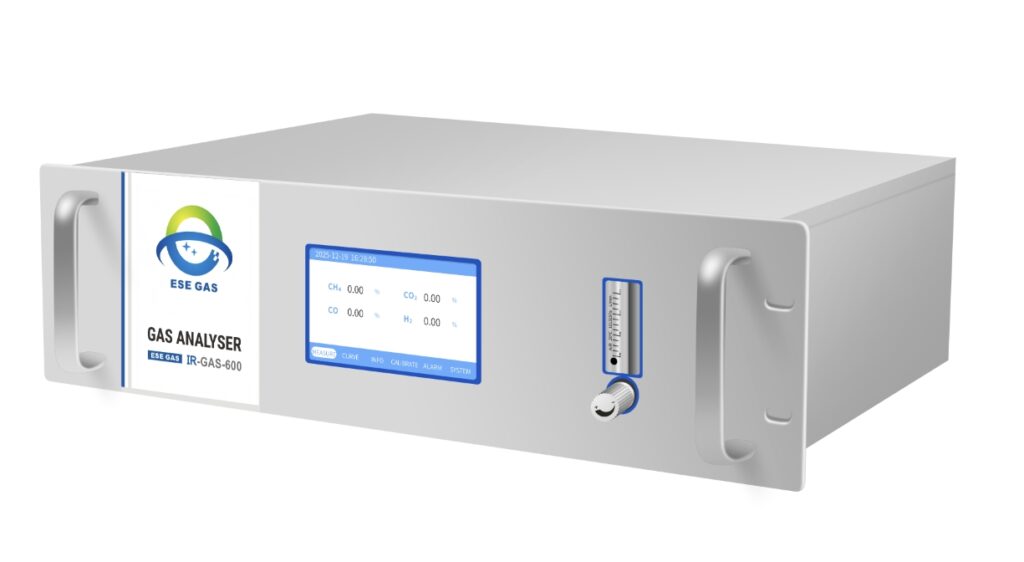
A practical configuration may combine:
- NDIR: Suitable for gases such as CO, CO₂ and CH₄.
- Thermal conductivity detection: Commonly used for hydrogen in an appropriate background gas.
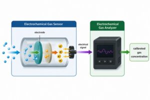
- Paramagnetic, zirconia or electrochemical measurement: Options for O₂, depending on range and installation conditions.
- FTIR: Useful when several infrared-active components must be measured together.
- Laboratory chromatography: Helpful for detailed hydrocarbon characterisation or method confirmation.
- Flow measurement: Needed when concentration must be converted into a release rate.
At ESEGAS, we can configure a process gas analyzer by combining suitable channels rather than assuming that one optical method covers the entire gas list. The expected background gas, minimum and maximum concentrations, pressure and sample condition must be confirmed first.
How Should Tar, Dust and Condensation Be Managed?
Raw pyrolysis gas can carry tar, particles and condensable vapours that quickly foul tubing, filters and optical cells. Excessive cooling can also remove hydrocarbons from the sample, while inadequate protection can damage the analyzer.
The conditioning strategy should balance analyzer protection with representative sampling:
- Keep the inlet and transport line at a controlled temperature where hot measurement is required.
- Minimise line length and dead volume.
- Use filtration suitable for the expected particle load.
- Avoid filter materials that adsorb target components.
- Provide condensate handling where a dry measurement is intended.
- Control sample pressure and flow.
- Include safe venting or sample return.
- Test recovery through the complete line.
- Establish cleaning intervals based on actual fouling.
- Record conditioning-system alarms with the analytical data.
For raw gas, a heated or diluted sampling approach may be necessary. For cleaned gas, a conditioned dry stream may allow a simpler NDIR-based configuration. The appropriate choice depends on which part of the process is being measured.
How Can Methane Results Be Expressed per Kilogram of Biochar?
A methane concentration by itself cannot show the total release or allow meaningful comparison between production batches. The result must be connected to gas flow, test duration and the amount of biochar produced.
A measurement campaign should record:
- CH₄ concentration over the sampling period.
- Gas flow at the measurement point.
- Temperature, pressure and moisture reference conditions.
- Duration of the release.
- Operating status and feed rate.
- Biochar production mass for the corresponding period.
- Bypass, startup and shutdown events.
- Calibration and instrument status.
The measured methane mass can then be divided by the corresponding biochar production to obtain grams of methane per kilogram of biochar. If hydrocarbons or CO are used to infer methane under certification guidance, the relationship and conservative assumptions must be documented.
How Can Gas Analysis Improve Pyrolysis Operation?
Collecting data only for an audit misses much of its operational value. Real-time trends can reveal developing problems before they reduce production efficiency or create an uncontrolled release.
Gas data can help operators:
- Detect oxygen ingress through seals or feed systems.
- Identify unstable heating or feedstock changes.
- Adjust gas recirculation and burner settings.
- Evaluate whether combustible gas is being recovered.
- Detect incomplete oxidation at the final treatment stage.
- Compare reactor settings with biochar yield and properties.
- Plan maintenance for filters, condensers and burners.
- Investigate startup, shutdown and upset events.
Low O₂ with stable combustible-gas trends may indicate controlled oxygen-limited operation, while an unexpected O₂ increase can signal leakage or sample dilution. Interpretation should use several gas channels and process variables rather than one alarm value.
How Should Gas Data Be Integrated into Carbon Removal MRV?
Process measurements, laboratory biochar tests and production records often sit in separate databases. If timestamps and batch identifiers do not match, the operator may be unable to show which gas result belongs to which production period.
For carbon removal MRV, we recommend linking:
- Production-unit identification.
- Feedstock type and batch.
- Reactor operating period.
- Gas concentration and flow records.
- Methane emission result.
- Biochar production mass.
- Energy consumption and co-product use.
- Biochar laboratory results.
- Calibration and maintenance records.
- Data corrections and uncertainty information.
The monitoring system should preserve raw data as well as calculated results. This makes it easier to update calculations when certification guidance changes and helps auditors trace a reported value back to its original measurement.
Biochar gas monitoring should connect three goals: controlling the reactor, using combustible gas efficiently and documenting releases that affect the net carbon-removal result. At ESEGAS, we recommend mapping each measurement point to a specific decision before selecting the analyzer. A combination of conditioned multi-gas analysis, flow information and batch-linked data can provide a stronger foundation for safe production, energy recovery and credible carbon-removal reporting.