

Introduction
Measure flow using ultrasonic technology with a configuration selected for the medium, pipe or duct geometry and operating conditions.
Measured parameter: Gas flow rate
| Operating Principle | Ultrasonic Time-of-Flight Method |
|---|---|
| Measured Variables | Industrial exhaust gases, process gas velocity, actual volumetric flow rate |
| Measurement Range | Velocity: 0–40 m/s (Temperature measurement range: 0–300 °C) |
| Velocity Measurement Accuracy | ±0.1 m/s |
| Temperature Measurement Accuracy | ±1 °C & ±1% FS |
| Repeatability | When V > 2 m/s: ±1%; When V < 2 m/s: ±0.02 m/s |
| Touchscreen Display | Displays measurement variables |
| Measurement Distance | Through-flow: 0.5 m–15 m; Single-end: Fixed distance of 0.4m |
| Medium Temperature | Standard type: –20 °C to +150 °C; High-temperature type: –20 °C to +300 °C |
| Installation Angle | 30°–60° depending on operating conditions |
| Analog Output | 4–20 mA, 3 channels |
| 3-channel interface modes | USB 1.0, 1 x RS485 |
| Supply Voltage | 220 VAC, 50 Hz |
| Air Supply Requirements | 0.4–0.6 MPa, oil-free and water-free, pipe diameter φ8 |
| Power | 75 W / 350 W (with purge fan) |
| Ambient Temperature | –20 °C to +55 °C |
| Process Requirements | Humidity ≤35%, dust concentration under standard conditions <100 g/Nm³, vibration velocity ≤7.1 mm/s RMS |
| Functional Grounding (FE) | ≤1 Ω |
| Main Unit | 300 × 400 × 130 mm, Weight: 7.5 kg |
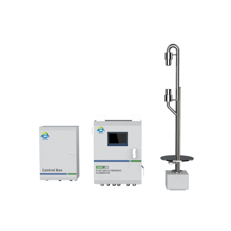
Integrating two probes, a control and calculation unit, provides a wealth of interfaces. We can expand the interface to different signal inputs and outputs, and can meet the needs of different occasions under the application.
ESEGAS Ultrasonic Flow Meter LEUF-200 for Flue Gas Application is to measure the flow rate of the gas; it can also calculate and output the volumeflow rate according to the flow rate and the flue size; if you input the temperature and pressure of the flue gas, you can calculate the flow rate under the standard conditions.
The transmit/receive probe consists of a piezoelectric ultrasonic generator and a receiver. The acoustic pulse and the direction of gas flow to form the angle α, the ultrasonic and gas flow direction counter-current and downstream transmission time is determined by the angle α and the gas flow velocity v. The larger the difference between the ultrasonic transmission time, the faster the gas flow rate, temperature and pressure fluctuations can cause the ultrasonic propagation speed changes, but in this measurement method, does not affect the calculation of the gas flow rate.
The Ultrasonic Flow Meter for Flue Gas Application measures the flow rate of gases discharged from ducts, flues, exhaust gases and flues; it can be used in both pure and raw gases; ie in closed circuits as well as in open gas circuits.
The Ultrasonic Flow Meter performs gas flow rate measurements by measuring the lag time of ultrasonic pulses. Meanwhile, we mount the transmitter/receiver probe on the side of the stack. And we orient the transmitter/receiver probe at a certain angle to the direction of gas flow.
| Operating Principle | Ultrasonic Time-of-Flight Method |
|---|---|
| Measured Variables | Industrial exhaust gases, process gas velocity, actual volumetric flow rate |
| Measurement Range | Velocity: 0–40 m/s (Temperature measurement range: 0–300 °C) |
| Velocity Measurement Accuracy | ±0.1 m/s |
| Temperature Measurement Accuracy | ±1 °C & ±1% FS |
| Repeatability | When V > 2 m/s: ±1%; When V < 2 m/s: ±0.02 m/s |
| Touchscreen Display | Displays measurement variables |
| Measurement Distance | Through-flow: 0.5 m–15 m; Single-end: Fixed distance of 0.4m |
| Medium Temperature | Standard type: –20 °C to +150 °C; High-temperature type: –20 °C to +300 °C |
| Installation Angle | 30°–60° depending on operating conditions |
| Analog Output | 4–20 mA, 3 channels |
| 3-channel interface modes | USB 1.0, 1 x RS485 |
| Supply Voltage | 220 VAC, 50 Hz |
| Air Supply Requirements | 0.4–0.6 MPa, oil-free and water-free, pipe diameter φ8 |
| Power | 75 W / 350 W (with purge fan) |
| Ambient Temperature | –20 °C to +55 °C |
| Process Requirements | Humidity ≤35%, dust concentration under standard conditions <100 g/Nm³, vibration velocity ≤7.1 mm/s RMS |
| Functional Grounding (FE) | ≤1 Ω |
| Main Unit | 300 × 400 × 130 mm, Weight: 7.5 kg |
We will contact you within 1 working day, please pay attention to the email with the suffix “[email protected]” .