



A chlor-alkali plant can maintain normal electrical load and production while a separator, seal or operating condition begins to deteriorate. If an unwanted gas crosses into the opposite product stream, the first visible sign may be poor product quality or an unsafe gas mixture. Well-positioned gas analyzers give operators an earlier and more specific indication of what is changing.
A chlor-alkali process gas monitoring system should normally measure hydrogen contamination in the chlorine stream and chlorine contamination in the hydrogen stream. Oxygen and moisture should be added where they affect process safety, drying performance, product quality or downstream use. The final gas list and alarm settings must be based on the cell technology and plant hazard assessment.

These measurements serve different purposes and may operate at very different concentration ranges. An analyzer selected for product-purity control may not be suitable for a rapid safety trip, while an area detector cannot replace a representative process measurement inside the gas line.
Why Does Chlor-Alkali Production Require Measurements on Both Sides of the Cell?
Monitoring only one product stream leaves half of the separation problem unseen. A change in pressure balance, membrane condition or gas handling can affect both streams, so electrolyzer gas purity should be evaluated as a connected system.
Electrolysis produces chlorine at the anode and hydrogen at the cathode, with caustic soda formed on the cathode side. A membrane or diaphragm keeps the chlorine separated from the hydrogen and caustic solution.
The most important measurements normally include:
| Stream | Main component | Important checks | Typical purpose |
|---|---|---|---|
| Wet chlorine | Cl₂ | H₂, O₂ and selected impurities | Early process diagnosis and safety |
| Dried chlorine | Cl₂ | H₂ and moisture | Compression, liquefaction or downstream quality |
| Raw hydrogen | H₂ | Cl₂, O₂ and moisture | Separation performance and safety |
| Treated hydrogen | H₂ | Limiting contaminants required by the user | Product release or fuel use |
| Vent or treatment gas | Process-dependent | Residual Cl₂, H₂ or other permitted components | Treatment control and emissions assessment |
The table is a starting point, not a universal specification. Cell design, pressure control, gas treatment and product destination determine which channels are needed.
What Should Be Measured in the Chlorine Stream?
High chlorine concentration does not prove that the stream is safe for compression or further processing. A small but changing hydrogen component may provide a more useful indication of separator deterioration than the chlorine percentage itself.
Hydrogen-in-chlorine monitoring is commonly considered where operators need to:
- Detect abnormal crossover from the cathode side.
- Track changes during startup, shutdown or load adjustment.
- Protect downstream drying, compression or liquefaction equipment.
- Compare individual cell-room sections or electrolyzer groups.
- Support operating alarms and independent protective functions.
Oxygen may also be monitored where it affects chlorine quality, downstream reactions or interpretation of hydrogen results. Moisture becomes particularly important after drying because wet chlorine is more corrosive and may be unsuitable for downstream equipment.
Alarm and trip values should come from the plant’s process-safety study and equipment design. We do not recommend copying a concentration limit from an unrelated facility.
What Should Be Measured in the Hydrogen Stream?
Measuring only bulk hydrogen can miss contamination that matters at a much lower range. Chlorine-in-hydrogen monitoring may therefore require a separate analytical channel from the main hydrogen measurement.
The hydrogen side may be evaluated for:
- Hydrogen concentration or purity.
- Trace chlorine indicating crossover or inadequate treatment.
- Oxygen indicating air ingress or incomplete purging.
- Moisture after cooling, separation or drying.
- Other impurities required by a fuel, synthesis or product specification.
The measurement range depends strongly on the sample location. Raw hydrogen can contain water vapour and entrained liquid, while purified hydrogen may require much lower detection capability. Using one analyzer alternately on both streams may also create long purge times or cross-contamination.
Where Should Process Samples Be Collected?
A sample point selected only because it is easy to reach may respond too slowly or fail to represent the gas entering critical equipment. Effective membrane leak detection requires the sample to be associated with the correct cell group and operating condition.
Possible measurement locations include:
- Individual electrolyzer or cell-group outlets: Provides early localisation of crossover.
- Combined wet-chlorine header: Shows the composition delivered to the cooling and drying system.
- After chlorine drying: Confirms moisture control before compression or liquefaction.
- Raw-hydrogen header: Supports separation-performance assessment.
- After hydrogen treatment: Confirms the quality sent to storage or downstream use.
- Absorber or treatment outlet: Supports residual-chlorine control where required.
- Vent and relief systems: Identifies releases outside the normal product route.
- Equipment areas: Uses independent fixed detectors for personnel and facility protection.
Combining many electrolyzers into one sample can dilute a local problem. Plants should balance centralised measurement with enough sectional information to identify where a change originated.
Which Analyzer Technologies Fit These Gases?
Neither hydrogen nor chlorine should be assigned to an analyzer simply because it can measure another process component. Their molecular properties require different analytical principles.
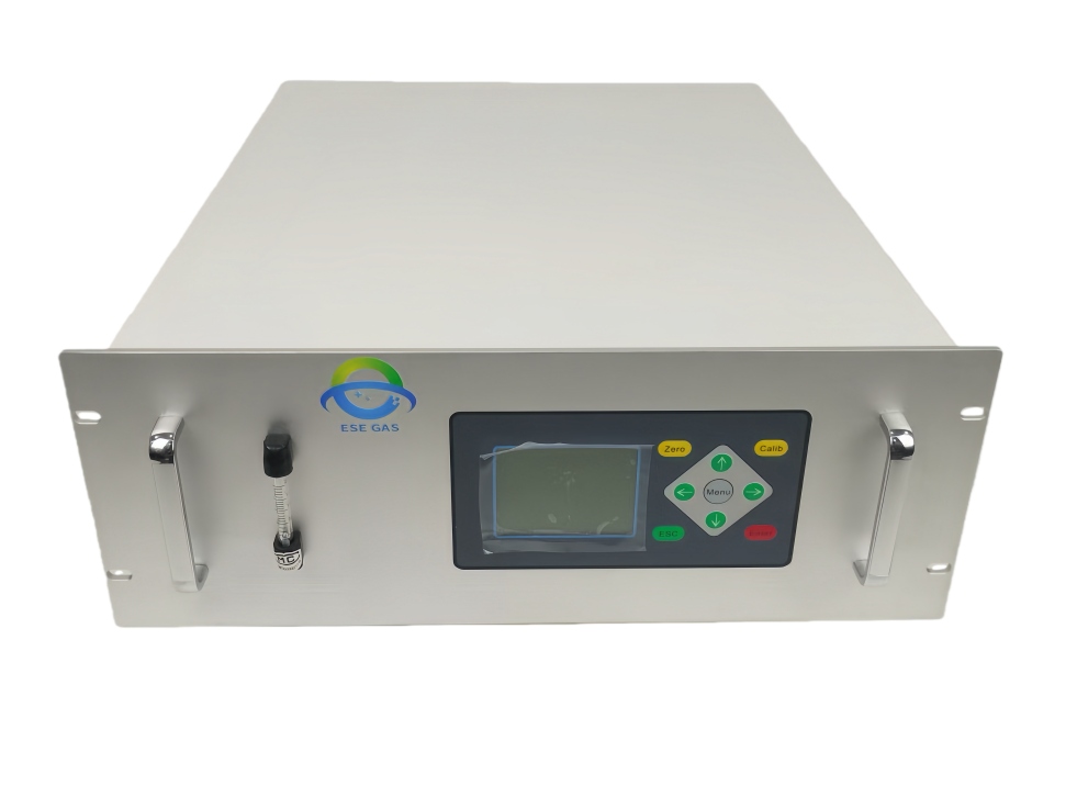
A chlor-alkali process analyzer may combine:
- UV absorption or differential optical absorption spectroscopy: Suitable for chlorine measurement when the range, gas matrix and optical configuration are validated.
- Thermal-conductivity measurement: Often used for hydrogen in a defined background gas.
- Paramagnetic, zirconia or electrochemical analysis: Possible options for oxygen, depending on range and sample condition.
- Moisture or dew-point analysis: Selected according to whether the measurement concerns wet process gas or dried product.
- Gas chromatography: Useful for detailed composition confirmation or periodic validation.
ESEGAS offers UV-DOAS chlorine analysis as one possible measurement channel. Because neither H₂ nor Cl₂ is suitably handled by a conventional infrared-only configuration, we normally combine dedicated technologies around the actual application instead of presenting one analyzer as a universal solution.
How Should the Sampling System Handle Wet and Reactive Gas?
An accurate detector cannot correct for a sample that changes inside the tubing. Chlorine can react with unsuitable wetted materials, while water and entrained caustic can create corrosion, blockage or biased results.
Reactive gas sample conditioning should address:
- Wetted-material compatibility.
- Representative probe position.
- Prevention or controlled removal of liquid carryover.
- Sample-line temperature.
- Pressure and flow regulation.
- Short transport volume for fast response.
- Filters that do not retain the target component.
- Safe discharge or return of the analyzed sample.
- Automatic purge arrangements.
- Access for cleaning and leak testing.
The conditioning strategy must match the analytical basis. If moisture is removed before analysis, operators should confirm that the target gas is not lost with the condensate. Where hot or wet measurement is retained, every downstream component must tolerate the sample.
How Can Operators Separate Process Control from Safety Detection?
Using one measurement channel for every purpose creates a single point of failure. It can also introduce a delay when a process analyzer cycles between sample locations.
A practical protection structure may include:
- Process analyzers for composition and long-term trends.
- Fast dedicated channels for critical cross-contamination.
- Independent area gas detectors.
- Ventilation and building-status signals.
- Pressure, flow and differential-pressure measurements.
- Hardwired protective functions where required by the safety design.
- A supervisory data system for diagnostics and maintenance.
The process analyzer can support an alarm or interlock, but its role, response time and failure behaviour must be defined by the responsible process-safety team. Maintenance mode and calibration gas should never be mistaken for a real process event.
How Should Measurement Performance Be Verified?
A stable display does not demonstrate that a reactive sample is reaching the analyzer correctly. Chlorine breakthrough detection is only dependable when the complete path is challenged and maintained.
Commissioning and routine quality controls should include:
- Zero and span verification with suitable standards.
- Challenge testing through as much of the normal sample path as practicable.
- Response and recovery-time measurement.
- Leak testing.
- Checks under normal and elevated moisture conditions.
- Verification of pressure and flow sensitivity.
- Cross-interference testing.
- Synchronisation with cell load, pressure and valve data.
- Documentation of calibration, maintenance and alarm tests.
- Comparison with an independent method where appropriate.
Trend data should be associated with the correct electrolyzer group and operating state. This allows operators to distinguish a real crossover trend from dilution, maintenance activity or analyzer drift.
Chlor-alkali process gas monitoring should provide an early view of gas separation, product treatment and abnormal operation. At ESEGAS, we recommend starting with the plant’s cell technology, measurement locations and safety functions, then combining dedicated Cl₂, H₂, O₂ and moisture channels with a sample system designed for the real gas conditions. This creates information that operators can use for both immediate protection and long-term process improvement.