



Hydrogen chloride (HCl) monitoring in waste-to-energy plants is challenging because hot, wet, dusty flue gas can affect sampling, response time, and measurement stability. Choosing the right TDLAS architecture helps plants obtain reliable continuous HCl data.
For waste-to-energy plants, both extractive and in-situ TDLAS can provide continuous HCl monitoring. Extractive systems transport a heated sample to an gas analyzer, while in-situ systems measure HCl directly across the flue-gas path. The better choice depends on gas conditions, installation access, measurement requirements, and CEMS design.
The difference looks simple on paper, but the engineering decision is more involved. HCl can interact with moisture, sampling surfaces, filters, and temperature changes. Therefore, the HCl analyzer itself is only one part of the measurement system.
Why Is HCl Measurement Difficult in Waste-to-Energy Plants?
Waste-to-energy flue gas rarely behaves like a clean laboratory gas. The composition can change with waste quality, combustion conditions, and flue-gas treatment.
HCl mainly comes from chlorine-containing materials in the waste stream. After combustion, the gas may contain HCl together with water vapor, dust, CO₂, SO₂, NOx, and other compounds. The main measurement risks include:
- High gas temperature
- High moisture
- Particulate matter
- Corrosive gas components
- Condensation
- HCl adsorption
- Sampling-system leaks
- Optical window fouling
- Changing gas concentration
Moisture deserves particular attention. If an extractive sampling system develops a cold spot, HCl can be affected by condensation and contact with the sampling surfaces. Consequently, the HCl analyzer may receive a sample that no longer represents the gas in the duct.
For this reason, EPA Performance Specification 18 treats the sampling interface, gas analyzer, reference gas system, moisture measurement, and other components as parts of the HCl CEMS rather than viewing the HCl analyzer as an isolated instrument.
This leads to an important engineering question: should the plant bring the gas to the analyzer, or bring the analyzer to the gas?
How Does a TDLAS HCl Analyzer Measure Hydrogen Chloride?
TDLAS stands for Tunable Diode Laser Absorption Spectroscopy. The technique measures gas concentration by detecting how a target molecule absorbs laser light at characteristic wavelengths.
For HCl measurement, the laser is tuned across an HCl absorption feature. When the laser passes through the gas, HCl absorbs part of the optical signal. The gas analyzer evaluates the absorption response and calculates the HCl concentration. In simple terms:
Laser → HCl absorption → optical signal change → concentration calculation
The optical path can be located inside an extractive measurement cell or directly across a process duct. That distinction is important because the same TDLAS principle can support two very different system architectures.
ESEGAS describes its online TDLAS gas analyzer as using selected gas absorption lines for continuous measurement of gases including HCl, HF, and NH₃. However, TDLAS should not be treated as a magic solution. The optical design, gas temperature, pressure, moisture, path length, sampling arrangement, and installation environment all influence the final measurement.
What Is the Difference Between Extractive and In-Situ TDL HCl Measurement?
The fundamental difference is where the measurement takes place. An extractive TDL online HCl analyzer removes a representative gas sample from the duct and transports it to the gas analyzer. An in-situ system measures the gas directly across an optical path in the stack or duct.
| Factor | Extractive TDL HCl Analyzer | In-Situ Wall-Mounted TDL HCl System |
|---|---|---|
| Measurement location | Analyzer measurement cell | Directly across the duct |
| Sample transport | Required | Not required |
| Heated sample line | Typically required | Not required for direct-path measurement |
| Sample conditioning | Application-dependent | Minimized |
| Main measurement risk | Sample loss or alteration | Optical path degradation |
| Maintenance focus | Probe, filter, line, pump, conditioning | Windows, purge, alignment, optical signal |
| Response delay | Includes sample transport | Primarily measurement-path dependent |
| Installation flexibility | Often higher | Depends strongly on duct geometry |
| Optical access | Not required across the process duct | Required |
| Best fit | Controlled extractive sampling | Suitable direct measurement points |
Neither architecture wins every application. Instead, the plant should select the architecture that preserves the most representative measurement with the least practical maintenance burden.
When Is an Extractive TDL Online HCl Analyzer a Better Choice?
An extractive TDL online HCl analyzer can be a strong choice when the plant needs controlled sample handling or when direct optical installation is difficult.
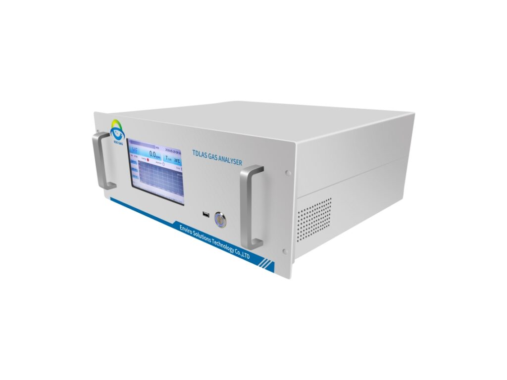
The typical configuration looks like this:
Flue gas → sampling probe → heated filter → heated line → sample conditioning → TDLAS analyzer → PLC/CEMS
The main advantage is control over the sample before it reaches the measurement cell. For example, the HCl analyzer can be installed in a more accessible location while the sampling system brings the gas from the stack or duct to the gas analyzer cabinet. However, that flexibility creates another responsibility: the sample must remain representative during transport.
EPA PS-18 specifies that an extractive CEMS sample-conditioning system must keep the particle-free gas above the dew point of its components. This requirement directly illustrates why temperature management matters in HCl extraction. Engineers should therefore check:
- Probe material compatibility
- Filter design
- Heated-line temperature
- Sample transport distance
- Dew point
- Condensation risk
- Sample flow stability
- Leakage
- Calibration-gas introduction
- Maintenance access
A long sampling line is not automatically a problem. A poorly controlled sampling line is. For HCl, that distinction matters because a measurement system can produce a stable number while still delivering a biased sample.
When Is an In-Situ Wall-Mounted TDL HCl Monitoring System a Better Choice?
An in-situ TDL HCl monitoring system becomes attractive when the duct provides suitable optical access and the plant wants to avoid sample transport.
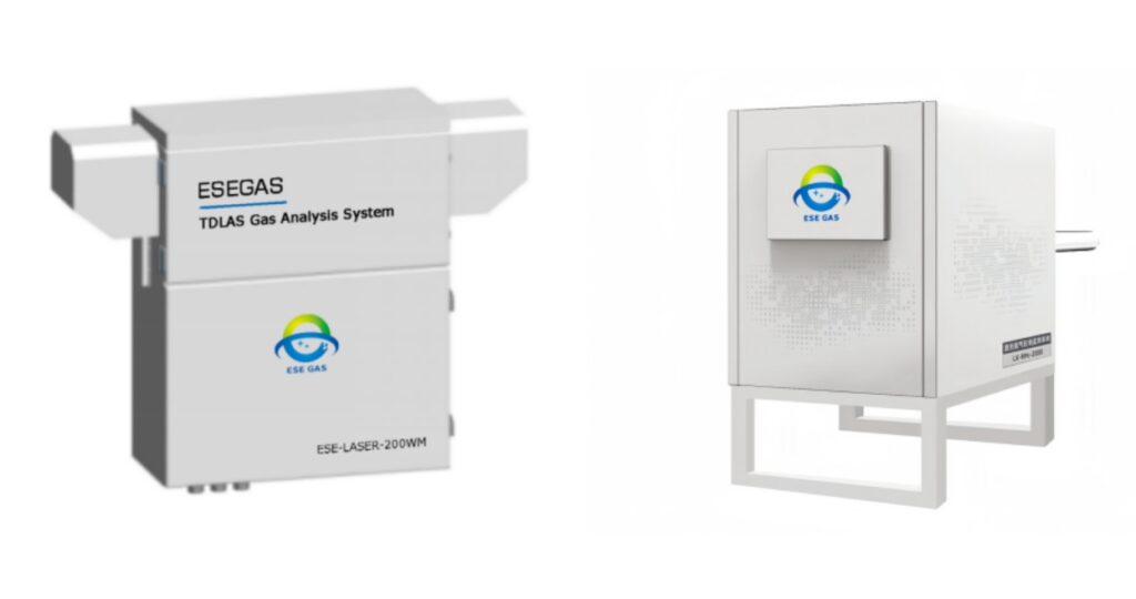
The measurement path is installed directly across the process gas. The laser travels through the flue gas, and the gas analyzer determines HCl concentration from the absorption signal. This architecture removes several components found in extractive systems: Long sample lines, Sample pumps, Conventional sample conditioning, and Sample transport delays.
As a result, in-situ measurement can provide a shorter measurement path from the process to the gas analyzer. However, it introduces its own engineering concerns. The plant must evaluate:
- Duct diameter
- Optical path length
- Gas temperature
- Gas pressure
- Dust loading
- Water vapor
- Optical-window fouling
- Vibration
- Alignmen
- Purge requirement
- Maintenance access
Dust is particularly important in waste-to-energy applications. Deposits on optical windows can reduce optical transmission and eventually affect measurement quality. Therefore, in-situ does not mean maintenance-free. Instead, it changes the maintenance problem from sample handling to optical-path management.
ESEGAS describes its in-situ TDLAS approach as suitable for demanding industrial environments, including high-temperature and high-dust applications.
Where Should an HCl Analyzer Be Installed in a Waste-to-Energy Plant?
The correct measurement point depends on the purpose of the measurement. A WTE plant may want HCl data for Combustion monitoring, Scrubber control, Process optimization, Emission monitoring, and Regulatory compliance. These objectives do not necessarily require the same measurement location.
For example, a measurement point before a flue-gas treatment system can help engineers understand the incoming HCl load. A downstream point can show how effectively the treatment system controls HCl. EPA PS-18 specifically addresses HCl CEMS performance and includes requirements covering measurement systems, calibration, interference testing, and integrated-path systems.
The key point is simple: do not select the gas analyzer first and the measurement point afterward. Select the measurement objective and point first, then design the gas analyzer system around them.
How Should an HCl Analyzer Be Integrated Into a Waste-to-Energy CEMS?
An HCl analyzer should work as part of the CEMS, not as a stand-alone box. A typical system includes:
Measurement → signal processing → data acquisition → data recording → plant control or compliance reporting
Depending on the project, the HCl analyzer may interface with: PLC, DCS, CEMS workstation, 4–20 mA loops, RS232/RS485, and Other digital communication systems. ESEGAS lists 4–20 mA and RS232/485 interfaces for the ESE-LASER-200 online HCl analyzer. Its published specifications also list a response time of less than 15 seconds at a gas flow rate of 3 L/min. For compliance applications, however, communication is only one part of the job.
EPA Procedure 6 establishes QA requirements for HCl CEMS used for compliance determination. These requirements include calibration-drift checks, maintenance procedures, accuracy audits, data recording, and corrective actions. For integrated-path HCl CEMS, the procedure also addresses beam intensity and temperature and pressure measurements. That means the plant should evaluate the HCl analyzer, QA/QC procedures, reference gases, data system, and maintenance plan as one package.
What Should Engineers Consider Before Selecting an HCl TDLAS System?
Before requesting a quotation, engineers should prepare the actual gas and installation data.
| Parameter | What should be provided? |
|---|---|
| Target gas | HCl and any additional gases |
| Range | Normal, minimum, and peak HCl |
| Temperature | Normal and maximum gas temperature |
| Pressure | Operating and design pressure |
| Moisture | Expected H₂O concentration |
| Dust | Approximate particulate loading |
| Gas composition | Major and interfering components |
| Measurement point | Duct, stack, upstream, or downstream |
| Installation | Extractive or in-situ preference |
| Response | Required response time |
| Output | 4–20 mA, RS485, PLC/DCS, etc. |
| Calibration | Required gas and QA/QC method |
| Maintenance | Available access and service conditions |
| Regulation | Applicable local or national requirements |
This information allows the HCl analyzer manufacturer to design the measurement system instead of simply matching a product name to a gas name.
How Does ESEGAS Design TDL HCl Monitoring Systems for Waste-to-Energy Plants?
ESEGAS approaches HCl measurement by matching the gas, concentration range, measurement point, sampling architecture, and plant interface to the application.
For waste-to-energy projects, ESEGAS offers TDLAS-based HCl solutions including ESE-LASER-200 online HCl analyzers, the ESE-LASER-200WM wall-mounted HCl monitoring system, and LX-2000 wall-mounted HCl monitoring system. The published ESE-LASER-200WM and LX-2000 specifications includes HCl ranges of 0–50 ppm, 0–100 ppm, and 0–500 ppm, with customized ranges available. The ESE-LASER-200 specification includes HCl ranges of 0-20 ppm, 0-200 ppm, and 0-2000ppb, with customized ranges available.
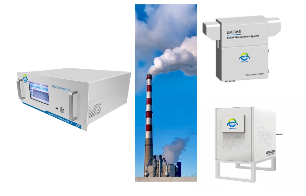
The ESE-LASER series also uses a high-temperature extractive configuration with sampling, transmission, preprocessing, control, and analysis units. ESEGAS specifically lists incineration and waste-incineration emission monitoring among its applications.
For projects that require direct in-situ measurement, ESEGAS also describes TDLAS in-situ gas monitoring system configurations for high-temperature and high-dust industrial environments. The final system should therefore be selected from the site conditions rather than from the product label alone.
Conclusion
Waste-to-energy plants should choose between extractive and in-situ TDL HCl monitoring based on gas conditions, measurement location, sampling risk, optical access, maintenance, and CEMS requirements. ESEGAS provides TDLAS HCl solutions for industrial applications and can help engineers match the analyzer architecture to the actual process conditions.
FAQs:
What Is a TDL Online HCl Analyzer?
A TDL online HCl analyzer uses Tunable Diode Laser Absorption Spectroscopy to continuously measure hydrogen chloride concentration. Depending on the system architecture, the HCl analyzer can measure an extracted sample in a measurement cell or measure HCl directly along an optical path in the process duct.
Why Is HCl Difficult to Measure in Waste-to-Energy Flue Gas?
HCl measurement can be affected by moisture, condensation, dust, temperature changes, corrosive components, and sampling-system losses. Therefore, engineers must consider the complete measurement system, not just the analyzer’s optical technology.
What Is the Difference Between Extractive and In-Situ HCl Measurement?
Extractive measurement removes flue gas from the duct and transports it to an analyzer. In-situ measurement analyzes the gas directly across an optical path in the duct. Extractive systems focus more on sample integrity, while in-situ systems require suitable optical access and optical-path maintenance.
Does Water Vapor Affect HCl TDLAS Measurement?
Water vapor can affect HCl measurement through sample condensation, gas-matrix effects, and optical interference depending on the system design. Extractive systems must control sample temperature and condensation risk, while in-situ systems must account for the actual flue-gas matrix.
What HCl Measurement Range Should a Waste-to-Energy Plant Use?
The range should cover the expected normal and peak HCl concentrations while providing suitable resolution and detection capability. ESEGAS currently lists 0–50 ppm, 0–100 ppm, and 0–500 ppm HCl ranges for its ESE-LASER-200WM, with customized ranges available.
Can a TDLAS HCl Analyzer Be Integrated Into a CEMS?
Yes. A TDLAS HCl analyzer can form part of a CEMS when its complete configuration meets the applicable monitoring and QA requirements. Integration can include analog and digital outputs, data acquisition, calibration, diagnostics, and plant or compliance systems.
Is In-Situ HCl Measurement Always Better Than Extractive TDLAS?
No. In-situ measurement can reduce sample transport and conditioning, but it requires suitable optical access and effective control of window fouling, alignment, purge, and installation conditions. Extractive TDLAS remains useful when controlled sample handling or centralized analyzer installation provides a better fit.
How Can ESEGAS Help Select an HCl Monitoring System?
ESEGAS can evaluate the target gas, measurement range, temperature, pressure, moisture, dust, installation point, sampling architecture, response requirement, calibration approach, and plant interface before recommending an HCl TDLAS configuration.