



A regenerative thermal oxidizer may maintain its specified temperature while an inlet valve leaks, a process batch overloads the unit or an organic compound responds poorly to the selected analyzer. If operators rely on temperature alone, they can miss releases that occur despite apparently normal thermal conditions. Direct gas measurements combined with operating parameters provide stronger evidence of actual performance.
Regenerative thermal oxidizer VOC monitoring should normally combine outlet VOC measurement and combustion-zone temperature with representative flow and operating data. When destruction efficiency must be demonstrated, corresponding inlet and outlet mass rates are required. The applicable permit and test method determine whether continuous gas monitoring, periodic performance testing or parametric monitoring is accepted.

Monitoring objectives should be separated before instruments are selected. A continuous trend can help operators detect deterioration, a formal stack test can establish performance under defined conditions, and a permit may use temperature or another parameter as the ongoing compliance indicator. These functions are related but not automatically interchangeable.
Why Is Temperature Alone Insufficient?
A high displayed temperature does not prove that every portion of the waste stream received adequate time and mixing in the combustion zone. Bypass leakage, measurement-location errors and rapid inlet changes can all weaken actual treatment while the temperature signal remains normal.
RTO destruction efficiency depends on the complete operating system, including:
- Actual gas temperature in the relevant combustion zone.
- Residence time.
- Mixing and turbulence.
- VOC identity and concentration.
- Oxygen availability.
- Exhaust flow.
- Burner and auxiliary-fuel condition.
- Bed and valve performance.
- Capture-system integrity.
- Bypass status.
Temperature is an important operating indicator and may be the required continuous parameter under a permit. It should be established during a valid performance test and measured at a representative location rather than copied from another installation.
How Should Destruction Efficiency Be Calculated?
Comparing inlet and outlet concentrations directly can produce the wrong result when the gas flow changes across the oxidizer. Air leakage, combustion air and auxiliary fuel can dilute the outlet even if the amount of organic material destroyed is lower than expected.
The calculation should use inlet and outlet VOC mass flow:

Each mass rate is derived from the relevant concentration and gas flow using compatible units, temperature, pressure and moisture conditions.
The test plan should define:
- Inlet and outlet sampling locations.
- Whether measurements are simultaneous.
- How transport delay is corrected.
- The organic measurement basis.
- Gas-flow measurement method.
- Moisture and oxygen corrections.
- Treatment of methane.
- Calibration compound and response basis.
- Duration and number of test runs.
- Operating conditions represented by the result.
Where a capture system is also being evaluated, overall control efficiency should not be confused with destruction efficiency inside the RTO.
Should the System Measure THC or Individual VOCs?
A single combined hydrocarbon value is useful for trending but may not represent every compound equally. Conversely, detailed speciation can be too slow for controlling a rapidly changing process.
A total hydrocarbon analyzer can provide continuous information using a flame ionization detector. Depending on the applicable method, the result may be expressed relative to propane, carbon or another calibration basis.
The monitoring plan may distinguish:
| Measurement | Typical purpose |
|---|---|
| THC or total gaseous organics | Fast inlet and outlet trends |
| NMHC | Separates methane where required |
| Specific VOCs | Confirms destruction of compounds named in a permit or process assessment |
| CO | Indicates incomplete combustion or abnormal oxidation |
| O₂ | Supports combustion and dilution interpretation |
| CO₂ | Provides additional combustion context |
| Gas flow | Converts concentration to mass rate |
The VOC response factor matters because an FID does not necessarily respond identically to every organic compound. Where the waste-gas composition changes, the calibration compound and method assumptions should be reviewed.
Gas chromatography, FTIR or laboratory methods may be added when compound separation or identification is required.
Where Should the Samples Be Collected?
An inlet sample taken before several process branches have mixed may not represent the gas entering the oxidizer. An outlet sample collected upstream of a bypass junction may also miss part of the atmospheric discharge.
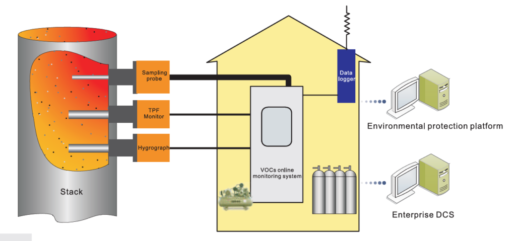
Suitable locations should provide:
- Adequate mixing.
- Access to representative gas flow.
- Clear separation between inlet and treated outlet.
- Limited air leakage.
- Safe maintenance access.
- Sufficient distance from severe flow disturbances.
- Corresponding process and RTO operating data.
Potential points include:
- The combined process-gas header before the RTO.
- Individual high-risk process branches.
- The oxidizer outlet before unrelated streams are added.
- The final stack.
- Bypass or emergency vents.
- Capture-system ducts used to verify collection performance.
Inlet and outlet readings should be corrected for sample-transport time. Without this correction, a high inlet pulse may be compared with an unrelated outlet period.
How Should Valve Switching and Batch Processes Be Monitored?
An average taken over several hours can hide short releases associated with bed reversal or production-cycle changes. These events may contribute a meaningful portion of total emissions even when the long-term average appears stable.
Potential valve-switching emissions should be investigated by synchronising gas readings with:
- Bed-reversal commands.
- Valve position.
- Chamber pressure.
- Fan current or airflow.
- Burner status.
- Process-batch start and stop times.
- Solvent loading.
- Bypass status.
- Analyzer response time.
For intermittent production, batch-cycle integration provides a better comparison than selecting one stable concentration. Inlet and outlet mass rates can be integrated over the corresponding batch period, provided that delay and data validity are handled consistently.
The analyzer and data system should be fast enough to capture the events relevant to the required averaging period. A slow multiplexed system may be suitable for general trends but unsuitable for a short valve-related peak.
Which Analyzer Technologies Can Be Used?
A method selected only because it measures “VOC” may provide incomplete information in a complex solvent mixture.
Possible technologies include:
- FID: Continuous measurement of total gaseous organic concentration under an applicable method.
- GC-FID: Separates selected compounds and can distinguish methane or target VOC groups.
- FTIR: Measures configured infrared-active organic and combustion components.
- Photoionization detection: Useful for selected process or screening applications but not automatically equivalent to a regulatory VOC method.
- Laboratory chromatography: Supports detailed speciation and method validation.
- Flow measurement: Provides the corresponding gas quantity for mass calculations.
US EPA Method 25A is one recognised FID-based method, but its use must follow the rule, permit and source-specific requirements that invoke it. An industrial analyzer should not be labelled “Method 25A compliant” solely because it contains an FID.
At ESEGAS, we can configure VOC, supporting gas and flow channels around the project objective. We first confirm whether the required result is THC, NMHC, a named compound, a mass rate or an operating trend.
How Should the VOC Sample Path Be Designed?
Condensation can remove organic compounds before they reach the detector, producing a stable but falsely low result. Long lines and contaminated filters can also flatten peaks and extend recovery time.
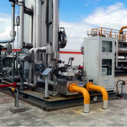
A heated VOC sample line may be required to maintain the sample above the relevant condensation condition. The complete sampling system should address:
- Probe and tubing materials.
- Aerosol and particulate control.
- Sample temperature.
- Line length and internal volume.
- Stable pressure and flow.
- Calibration-gas introduction.
- Safe disposal of sampled gas.
- Line cleaning and filter replacement.
- Recovery after high concentrations.
- Analyzer protection during an over-range event.
The system should be tested using representative compounds through as much of the normal sample path as practicable. Detector-only calibration cannot identify losses in tubing, filters or valves.
Which Operating Parameters Should Be Recorded?
VOC readings are difficult to diagnose when they are stored separately from the oxidizer control system. A unified data structure allows an emission change to be associated with the condition that caused it.
Useful parameters include:
- Combustion chamber temperature at the defined monitoring location.
- Inlet and outlet VOC readings.
- Exhaust flow.
- O₂, CO and CO₂ where used.
- Burner firing rate.
- Auxiliary-fuel pressure or flow.
- Fan current and duct pressure.
- Bed and valve status.
- Process production rate.
- Bypass and alarm signals.
- Analyzer calibration and maintenance status.
Quality assurance should include zero and span checks, response-time testing, flow verification, clock synchronisation and controlled configuration changes. Raw values and validity flags should be retained together with calculated averages and efficiency results.
Reliable regenerative thermal oxidizer VOC monitoring requires more than one temperature signal or one outlet concentration. At ESEGAS, we recommend defining whether the project needs compliance evidence, performance testing or operational diagnostics, then matching the analyzer, flow measurement, sampling path and RTO data to that purpose. This creates a traceable basis for evaluating treatment performance without overstating what any single measurement can prove.