



Biomass boilers can convert renewable fuels into useful heat and steam, but their emission profiles are rarely stable. Changes in fuel moisture, ash content, feeding rate, combustion temperature, and air distribution can quickly alter NOₓ, SO₂, CO, and other flue gas concentrations. When the monitoring system responds too slowly or produces unstable readings, operators may miss combustion problems, overuse denitrification reagents, or discover an emission exceedance only after it has occurred. UV differential optical absorption technology provides the continuous, selective measurements needed to turn these fluctuating emissions into reliable process information.
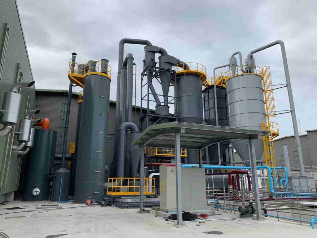
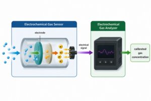
A UV differential gas analyzer improves biomass boiler flue gas monitoring by identifying the characteristic ultraviolet absorption spectra of gases such as SO₂, NO, NO₂, and NH₃. It provides fast, continuous, and selective concentration measurements that help operators verify emission compliance, optimize combustion, control SNCR or SCR systems, and detect abnormal boiler conditions.
However, selecting an ultraviolet analyzer alone does not guarantee accurate results. Biomass flue gas may contain substantial moisture, fly ash, condensable compounds, and rapidly changing pollutant concentrations. Reliable monitoring therefore depends on the analyzer technology, sample extraction method, gas conditioning design, calibration strategy, and integration with the boiler control system. Understanding how these elements work together is essential before configuring a complete monitoring solution.
What Makes Biomass Boiler Flue Gas Difficult to Monitor?
A UV Differential Gas Analyzer may offer strong selectivity, but it must still operate within a monitoring system designed for the actual boiler conditions. If the fuel changes from dry wood pellets to wet wood chips, agricultural residue, bark, or mixed biomass, the combustion process can change significantly. Without suitable sampling and conditioning, these variations may lead to condensation, filter blockage, delayed response, or unstable readings.
The main monitoring challenges include the following.
Variable biomass fuel composition
Biomass is not a uniform fuel. Its nitrogen, sulfur, chlorine, ash, and moisture content can vary by source, season, storage condition, and processing method. These changes influence both combustion behavior and pollutant formation.
For example:
- Higher fuel nitrogen may contribute to increased fuel-NOₓ formation.
- Sulfur-containing feedstock may increase SO₂ emissions.
- High moisture can reduce furnace temperature and destabilize combustion.
- High ash content can increase particulate loading in the flue gas.
- Agricultural residues may introduce more alkali metals and chlorine than clean wood fuels.
For this reason, a monitoring system should be selected according to the full expected operating range rather than only the emissions observed under ideal fuel conditions.
High moisture and condensation risk
Water vapor is a normal combustion product, while wet biomass introduces additional moisture into the process. If extracted flue gas cools below its dew point, condensate may form inside the probe, sample line, filter, or analyzer cabinet.
Condensation can cause several problems:
- Soluble gases may be partially removed from the sample.
- Moisture may collect inside tubing and create an unstable gas flow.
- Corrosive condensate may damage system components.
- Dust and water can combine to form deposits that block the sample path.
- The measured concentration may no longer represent the actual stack gas.
The sample line temperature, cooling method, drainage arrangement, and material selection must therefore be coordinated with the target gases.
High particulate loading
Biomass combustion can generate fly ash, soot, unburned particles, and fine aerosols. These contaminants can gradually restrict sample flow or reduce optical intensity if they reach sensitive components.
A practical monitoring system may require:
- A heated sampling probe
- Primary filtration at the stack
- Secondary fine filtration
- Automatic probe blowback
- Differential-pressure monitoring
- Accessible filters for routine maintenance
The correct arrangement depends on particle concentration, particle size, sampling location, and required response time.
Rapidly changing combustion conditions
Biomass feeding is not always perfectly uniform. Fuel bridging, variations in particle size, grate movement, air-distribution problems, and load changes can cause rapid fluctuations in oxygen, carbon monoxide, and nitrogen oxide concentrations.
A slow analyzer may smooth out these short-term events. A faster measurement allows operators to see when the process begins to deviate and respond before the deviation becomes a prolonged efficiency or compliance problem.
How Does UV Differential Optical Absorption Spectroscopy Work?
Complex flue gas contains many components, so measuring total light loss is not enough to identify one specific pollutant. Dust, optical aging, and broad background absorption can all reduce transmitted light. UV-DOAS addresses this problem by focusing on the narrow, structured absorption features that distinguish one gas molecule from another.
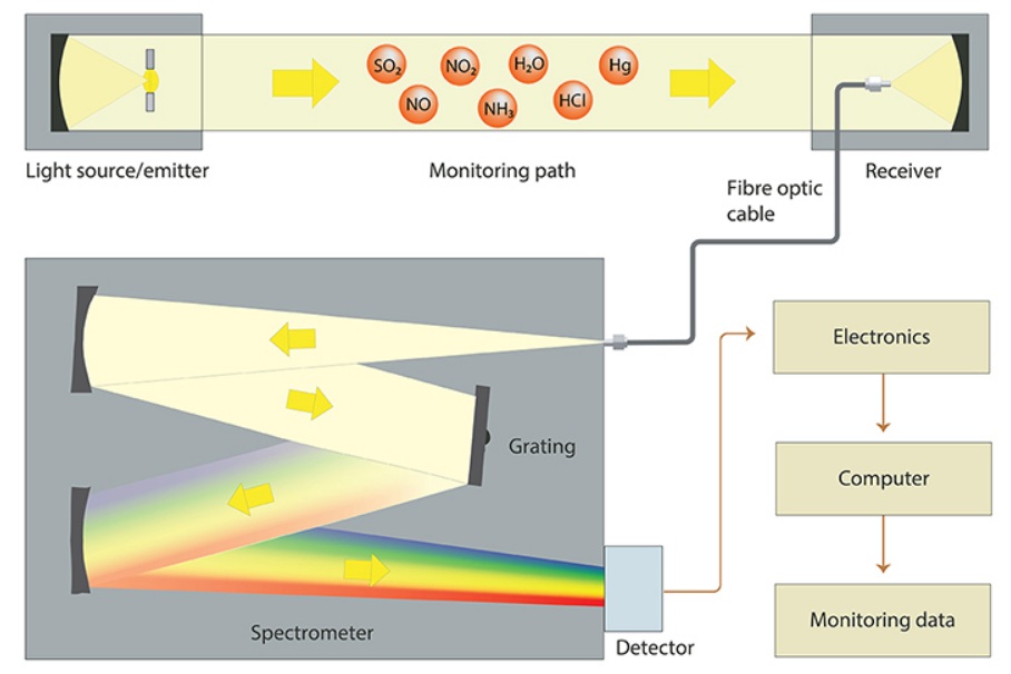
Inside a UV Differential Gas Analyzer, the measurement normally follows this sequence:
- A broadband ultraviolet light source emits light across a selected wavelength range.
- The light passes through a gas cell containing the conditioned flue gas sample.
- Target molecules absorb ultraviolet light at characteristic wavelengths.
- A spectrometer measures the transmitted light intensity.
- The software separates broad background attenuation from narrow differential absorption structures.
- Reference spectra and mathematical fitting are used to calculate the concentration of each target gas.
- The results are transmitted to a PLC, DCS, data-acquisition system, or CEMS platform.
The simplified process is:
Flue Gas Extraction → Filtration and Conditioning → UV Measurement Cell → Spectral Processing → Gas Concentration → CEMS or Boiler Control System
Which Gases Should Be Monitored in Biomass Boiler Flue Gas?
Monitoring only one pollutant provides an incomplete picture of boiler performance. A high NOₓ value may indicate a combustion or denitrification problem, while elevated CO may reveal incomplete combustion even when regulated pollutant concentrations remain within their limits. The correct gas combination should therefore reflect the fuel, boiler design, treatment process, and local reporting requirements.
A typical biomass boiler monitoring configuration may include:
| Gas component | Primary monitoring purpose | What the result can indicate |
| SO₂ | Emission monitoring | Sulfur input from fuel and sulfur conversion during combustion |
| NO | NOₓ measurement | Formation of nitrogen oxides during combustion |
| NO₂ | Direct NOₓ calculation | Changes in the NO-to-NO₂ distribution |
| NH₃ | Ammonia-slip monitoring | Excess or insufficient reagent control in SNCR or SCR |
| CO | Combustion optimization | Incomplete combustion or insufficient mixing |
| CO₂ | Process and combustion analysis | Fuel conversion and combustion trends |
| O₂ | Excess-air control | Air-to-fuel ratio and combustion-air distribution |
Why Is a UV Differential Gas Analyzer Suitable for Biomass Boiler Monitoring?
Biomass boilers need more than an occasional spot measurement. Fuel and load conditions can change throughout the day, so operators need continuous data that reveals trends, transient events, and treatment-system performance. A properly configured UV Differential Gas Analyzer offers several advantages for this application.
It can measure multiple UV-absorbing gases
SO₂, NO, NO₂, and selected additional gases have characteristic absorption structures in the ultraviolet region. A spectral instrument can evaluate more than one component from the recorded spectrum, reducing the need for a completely separate analyzer for every UV-active gas.
The final gas combination still depends on:
- Expected concentration ranges
- Potential spectral overlap
- Measurement-cell path length
- Spectrometer resolution
- Required detection limits
- Background gas composition
Configuration should therefore be based on application data rather than a generic multi-gas list.
It can measure NO and NO₂ separately
Direct measurement provides a clearer picture of total NOₓ than a system that measures only NO and assumes a fixed NO₂ fraction. It can also eliminate the need for an external NO₂-to-NO converter in suitable configurations.
This is valuable when:
- Fuel composition changes frequently
- Combustion temperature varies
- Flue gas treatment affects the NO/NO₂ ratio
- Low emission limits require better NOₓ resolution
- Converter maintenance would increase system complexity
It provides fast continuous data
Optical analysis can produce frequent concentration updates without waiting for a consumable chemical reaction. Faster data helps the control team identify combustion disturbances and evaluate the immediate effect of air, fuel, or reagent adjustments.
It reduces dependence on consumable reagents
UV-DOAS is an optical measurement method. Routine operation does not depend on the continuous consumption of analytical reagents, although calibration gases and maintenance materials are still required.
It supports modular multi-technology systems
No single technique is best for every flue gas component. A modular platform allows us to use:
- UV-DOAS for SO₂, NO, and NO₂
- NDIR for CO and CO₂
- Paramagnetic, zirconia, or another suitable method for O₂
- A dedicated technology where a difficult trace gas requires special handling
This configuration gives users a more complete view of combustion and emissions without forcing every component into one unsuitable measurement principle.
How Should a UV Differential Gas Analyzer Be Installed in a Biomass Boiler CEMS?
Even a high-performance analyzer can produce poor data when the sample reaching it is wet, contaminated, unrepresentative, or delayed. The sample-handling system is therefore part of the measurement—not simply an accessory added after the analyzer has been selected.
A typical extractive system contains the following elements:
- Sampling probe: Extracts a representative sample from the stack or duct.
- Primary filter: Reduces the particulate load entering the sample line.
- Heated sample line: Prevents premature condensation during transport.
- Gas conditioning unit: Controls moisture, temperature, pressure, and cleanliness.
- Analyzer module: Measures the required gas concentrations.
- Sample pump: Maintains a stable flow through the system.
- Flow and pressure controls: Detect restrictions and stabilize measurement conditions.
- Zero and span calibration system: Supports routine quality checks.
- Automatic blowback system: Clears accumulated dust from the probe where necessary.
- Data-acquisition interface: Sends results to the CEMS, PLC, DCS, or environmental reporting platform.
What Measurement Problems Commonly Occur in Biomass Flue Gas Applications?
When readings become unstable, replacing the analyzer is not always the correct first response. Many problems originate in the sampling system, calibration arrangement, or process conditions.
| Measurement problem | Possible cause | Recommended action |
| Slow response | Long sample line, low flow, blocked filter, oversized gas volume | Check flow, shorten the path where possible, and inspect filters |
| Gradual loss of optical intensity | Dust or deposits in the gas cell | Improve filtration and clean the optical cell |
| Unstable readings | Condensation, pump pulsation, pressure fluctuation, air leakage | Check heating, drainage, seals, and flow control |
| Frequent probe blockage | High fly-ash loading or inadequate blowback | Upgrade probe filtration and optimize automatic cleaning |
| Unexpected concentration bias | Spectral interference, incorrect range, unsuitable reference spectrum | Review the gas matrix and application calibration |
| Calibration failure | Incorrect gas concentration, insufficient purge time, leakage | Verify calibration gas, valves, tubing, flow, and stabilization time |
| NH₃ reading lower than expected | Adsorption, sample-line cooling, condensate loss | Use heated components and suitable wetted materials |
| Increasing drift | Optical contamination, lamp aging, temperature instability | Inspect the cell, verify temperature control, and recalibrate |
ESEGAS maintenance guidance identifies optical-intensity decay caused by contamination inside the gas chamber as a practical issue that can be corrected through proper cleaning and subsequent calibration. (Esegas)
How Can ESEGAS Support Biomass Boiler Flue Gas Monitoring?
Every biomass project has a different combination of fuel, boiler design, pollutant concentration, gas-treatment process, and environmental target. A fixed analyzer package may work for one plant but create unnecessary limitations in another. At ESEGAS, we therefore begin with the process conditions and build the measurement configuration around them.
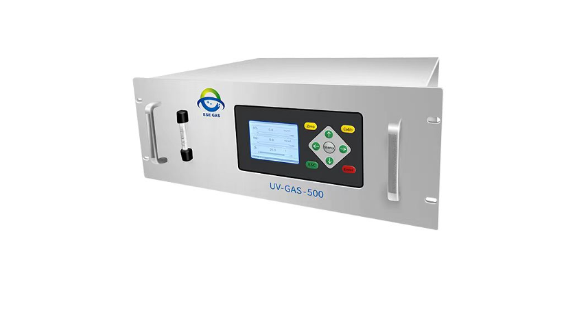
Our UV-GAS-500 platform can be configured as a UV Differential Gas Analyzer for components such as SO₂, NO, and NO₂. Direct NO and NO₂ measurement enables NOₓ calculation without relying on a separate NO₂-to-NO converter. Depending on the project, we can combine the UV module with NDIR measurement for CO and CO₂ and a suitable O₂analyzer to create a more complete flue gas monitoring system. (Esegas)
Our engineering evaluation can cover:
- Target gas selection
- Customized measurement ranges
- Hot-wet or cold-dry sample handling
- Heated sampling probes and lines
- Filtration and automatic blowback
- Calibration-gas arrangements
- Analyzer cabinet design
- Signal and communication interfaces
- Integration with CEMS, PLC, or DCS
- Operation and maintenance planning
We also consider whether the system will be used mainly for regulatory monitoring, combustion optimization, denitrification control, troubleshooting, or a combination of these functions. This distinction matters because the best sampling point, response time, range, and data-processing strategy may be different for each objective.
Conclusion
Biomass boiler emissions can change quickly because fuel moisture, composition, feeding stability, combustion air, and boiler load are rarely constant. A properly configured UV Differential Gas Analyzer provides continuous measurement of key ultraviolet-absorbing gases such as SO₂, NO, and NO₂, while additional modules can extend the system to CO, CO₂, O₂, and application-specific components. The analyzer itself is only one part of reliable monitoring: representative sampling, suitable gas conditioning, temperature control, filtration, calibration, and regular maintenance are equally important. At ESEGAS, we combine these elements into application-specific flue gas monitoring solutions that help biomass boiler operators improve combustion, optimize denitrification, maintain dependable emission records, and respond to abnormal conditions with greater confidence.