



A CO₂ electrolyzer can draw the expected current while producing a gas mixture that does not match the process target. Electrode flooding, catalyst change, air ingress and variable feed purity can shift the outlet before electrical data alone reveals the problem. Without representative gas measurements, operators cannot distinguish useful conversion from an unwanted side reaction.
A CO₂-to-CO electrolysis system should normally measure carbon monoxide, hydrogen, remaining carbon dioxide, oxygen and moisture, together with the corresponding gas flow. Methane, ethylene and other products should be added when the catalyst and process can form them. The required ranges and methods depend on the cell design and intended product.
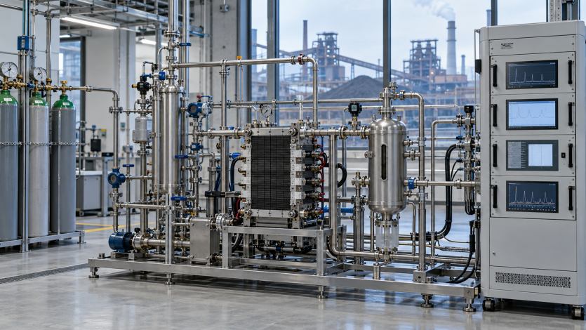
Gas composition becomes valuable only when it is connected to current, pressure, feed rate and the correct sampling location. The analytical design must therefore cover both steady production and the rapid changes that occur during start-up, load shifts and feed disturbances.
Why Is Gas Composition Essential to CO₂ Electrolysis?
Voltage and current show that an electrochemical reaction is occurring, but they do not identify the products. The same electrical input can support the target conversion, hydrogen evolution or other pathways.
The electrolyzer product gas contains the target compound, unconverted carbon dioxide and possible side products. For a CO-selective cathode, the hydrogen by-product is especially important because it consumes charge and changes product quality. Oxygen from the anode should be monitored separately where it is collected or used.
A complete analytical picture supports performance calculation, catalyst diagnosis and downstream control. It can also reveal gas crossover or air ingress, but the analyzer should not be treated as an independent safety system unless its response, failure behaviour and protective function have been formally assessed.
Which Gases Should Be Measured?
Using a fixed gas list for every cell can omit catalyst-specific products or add unnecessary channels. The list should begin with the intended reaction pathway and then cover the most likely competing reactions and balance gases.
| Component | Why it matters |
| CO | Target product for CO-selective systems and input to performance calculations |
| H₂ | Competing cathodic product and product-quality variable |
| CO₂ | Feed component and unconverted carbon used in conversion and carbon-balance calculations |
| O₂ | Anode product, crossover indicator or evidence of air ingress depending on location |
| H₂O | Sample basis, separator performance and condensation control |
| CH₄, C₂H₄ or other products | Catalyst-specific products requiring separation and compound-specific calibration |
| N₂ or tracer gas | Dilution, leakage assessment or flow normalisation when deliberately used |
The permanent channels should reflect the process rather than every product reported in laboratory literature. Periodic broad analysis can confirm whether a new product has appeared as the catalyst ages or the operating window changes.
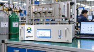
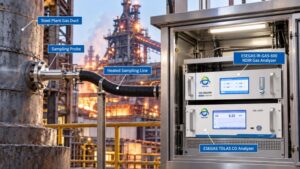
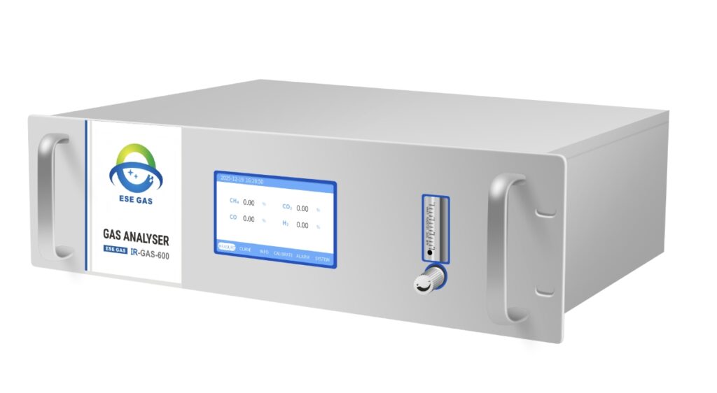
At ESEGAS, we can combine bulk-gas channels for CO, CO₂, H₂ and O₂ around the expected matrix. Where product speciation is more complex, online gas chromatography or another separation method should complement rather than be replaced by the bulk analyzer.
Where Should the Gas Be Sampled?
A single product-line measurement may show that quality is off target without identifying whether the feed, cathode, separator or recycle loop caused the change. Multiple well-defined boundaries make troubleshooting faster.
| Sampling point | Primary question |
| CO₂ feed | Is concentration and impurity loading stable? |
| Cathode outlet | What products are generated and what remains unconverted? |
| Anode outlet | Is oxygen production stable and is crossover occurring? |
| Separator outlet | What dry product reaches analysis or purification? |
| Recycle gas | Are inert or by-product gases accumulating? |
| Final product | Does composition meet the downstream process requirement? |
Possible locations include the conditioned CO₂ feed, cathode outlet, anode outlet, gas-liquid separator outlet, recycle stream and final product gas. A gas-liquid separator should remove entrained electrolyte or water before a dry-gas analyzer, but it must not lose target components or create an unmeasured vent.
The cathode and anode streams should normally remain distinct. Any crossover measurement must use ranges suited to the low-level component and materials compatible with moisture and electrolyte. If one analyzer switches between points, line purging and transport time must be included in the data flags.
Which Analyzer Technologies Fit the Process?
No single technique measures hydrogen, oxygen, carbon oxides and multiple hydrocarbons equally well. A practical system combines fast bulk analysis with separation when compound identity matters.
NDIR can measure configured infrared-active gases such as CO and CO₂. Thermal-conductivity detection can measure bulk hydrogen in a defined background. Paramagnetic, zirconia or electrochemical methods may be used for oxygen depending on concentration and sample conditions. Moisture requires a method selected for the expected dew point and pressure.
Online gas chromatography separates CO, CO₂, H₂, CH₄, ethylene and other configured gases, making it useful for product speciation and calibration of faster trend instruments. Mass spectrometry can respond quickly to load-change response, but overlapping mass fragments and background changes require careful calibration and, where possible, chromatographic confirmation.
- Use continuous bulk channels for fast control variables.
- Use chromatography for compound separation and quantitative product distribution.
- Use mass spectrometry for high-speed research and transient diagnosis when spectral overlap is controlled.
- Measure corresponding gas flow if composition will be converted into production or efficiency metrics.
- Retain independent laboratory confirmation for method development and unusual products.
How Should Gas Data Be Converted into Performance Metrics?
A high CO percentage can result from real production, low total flow or dilution changes. Concentration by itself cannot show how much product is formed or how effectively electrical charge is used.
CO Faradaic efficiency is calculated from the molar CO production rate, the electron requirement of the reaction and the electrical current. That means the calculation needs calibrated composition, representative product-gas flow and time-aligned current. The same principle applies to other gaseous products, using their reaction stoichiometry.
A mass-flow balance should also compare carbon entering as CO₂ with carbon leaving in CO, unconverted CO₂, hydrocarbons, liquid products and any vent or purge. Apparent carbon loss may indicate an unmeasured liquid product, carbonate formation, dissolved gas, a flow error or a leak rather than missing gas alone.
- Preserve the wet or dry basis of each concentration.
- Use compatible temperature and pressure reference conditions.
- Align gas composition, flow and current timestamps.
- Include purge, recycle and separator vents in the boundary.
- Report uncertainty and data gaps with each calculated efficiency.
How Should Moisture and Pressure Be Managed?
Product gas can leave the cell wet and at a pressure different from the analyzer requirement. Uncontrolled cooling can create liquid carryover, while aggressive drying can remove a soluble or condensable product.
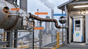
The sample system should define whether results are reported on a wet or dry basis. A controlled separator, cooler or membrane may protect the analyzer, but its recovery must be tested for every target. Lines should minimise dead volume so that rapid changes are not delayed or mixed.
Pressure reduction should avoid unstable flow and back-diffusion. Materials must tolerate water, electrolyte mist and any alkaline or acidic carryover. Drain status, filter pressure drop and separator alarms should be stored with the gas data because a conditioning fault can imitate a catalyst change.
What Changes When Real Industrial CO₂ Is Used?
A cell that performs well with bottled carbon dioxide may respond differently to captured industrial gas. Residual oxygen, nitrogen, sulfur or nitrogen oxides, moisture and solvent traces can affect the catalyst, membrane and analytical result.
Industrial trials reported in October 2026 are testing low-temperature CO₂ electrolysis with steel-industry flue gas after amine capture, while the four-year REACT project launched in May 2026 includes impurity-tolerant electrochemical conversion. These projects make feed characterisation and impurity tracking a practical scale-up need rather than only a laboratory question.
The feed review should identify CO₂ concentration, O₂, N₂, water and process-specific impurities before selecting ranges. Sulfur or nitrogen compounds may require dedicated trace methods. Solvent carryover from capture should be assessed separately because a bulk CO₂ analyzer may not reveal it.
- Establish a baseline with the purified design feed.
- Introduce real-gas impurities in a controlled and documented sequence where testing permits.
- Track catalyst selectivity, pressure drop and membrane behaviour together.
- Repeat calibration when the background-gas matrix changes materially.
- Do not assume that a product analyzer is also an impurity-tolerance test system.
How Should Start-Up and Load Changes Be Captured?
A slow analyzer can average away the first minutes of cell operation, even though that is when wetting, catalyst state and side reactions may change quickly. The system response must match the control question.
Research published in 2025 demonstrated thirty-second gas-chromatography sampling combined with faster mass spectrometry to examine dynamic CO₂ electrolysis. The result is not a universal cycle-time requirement, but it shows why start-up and current steps may need much faster analysis than steady-state certification.
The plant should measure transport delay through the complete path and time-synchronise electrical, flow, pressure and gas data. Over-range, purge and valve-switching periods should be flagged. A fast detector connected through a long, low-flow line is not a fast process measurement.
What Quality Controls Are Needed?
Small flow or calibration errors can produce large errors in calculated efficiency. Plausible percentages are not enough when the result is used to compare catalysts or accept a pilot plant.
Commissioning should include zero and span checks, multipoint calibration, representative background gas, leak testing, flow verification and response-time measurement. Chromatographic retention and detector response should be confirmed for every reported product. Mass-spectral fragmentation corrections should be validated against an independent method.
At ESEGAS, we recommend retaining raw analyzer signals, calibration records, product-gas flow, current and instrument status. The complete calculation should be reproducible from those records, and the system should be revalidated after a catalyst, separator, membrane or feed-conditioning change.
CO₂ electrolysis gas analysis should identify what the cell produces, how much charge forms each product and whether the carbon balance closes. At ESEGAS, we recommend combining fast CO, CO₂, H₂ and O₂ channels with product-specific chromatography, reliable flow measurement and a sample system designed for wet electrochemical gas. When the analytical data are aligned with current, pressure, feed purity and operating mode, they provide a stronger basis for catalyst development, pilot control and industrial scale-up.