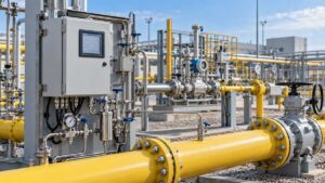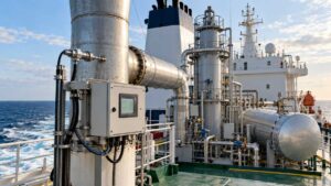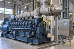




A ship may store a substantial quantity of captured carbon dioxide while still releasing more greenhouse gas than expected through the exhaust, a bypass or the energy required to operate the capture equipment. If performance is judged only from tank inventory, operators may overlook changing exhaust flow, incomplete capture or operating periods when the system was unavailable.
Onboard carbon capture monitoring should measure CO₂ concentration and gas flow at the relevant inlet and atmospheric outlet, quantify the captured CO₂ stream, and record bypass, storage and offloading conditions. Additional gases should be included where they affect environmental performance, process control or the selected verification method.

The complete design must follow the vessel’s machinery, fuel and capture technology. International rules for onboard systems are still developing, so a current industry recommendation should not be described as a final IMO compliance requirement. Shipowners should confirm flag, class, port and applicable regulatory expectations before approving the measurement plan.
What Is the Current Regulatory Position?
Installing a marine carbon capture system without a defined accounting boundary can create impressive capture figures that cannot be independently verified. Consistent OCCS verification requires agreement on what enters the system, what is stored, what reaches the atmosphere and which auxiliary effects belong in the calculation.
At its 84th session in April and May 2026, the IMO Marine Environment Protection Committee continued developing a regulatory framework for onboard carbon capture and storage. It adopted a revised work plan aimed at completing the work in 2028 and agreed that specific methodological guidance on accounting, verification and certification should be developed.
This means operators should distinguish between:
- Current MARPOL requirements that already apply to the vessel.
- Flag-state and class requirements.
- Project-specific testing or demonstration criteria.
- Voluntary recommended practices.
- Future IMO accounting and certification provisions.
- Port rules governing captured CO₂ transfer and reception.
DNV-RP-0698, published in June 2026, offers one current measurement framework based on mass balance. It is useful engineering guidance, but it is not a substitute for future IMO rules or a vessel’s approved statutory arrangements.
Which Boundaries and Gas Streams Should Be Included?
Measuring only across the absorber can hide emissions produced by regeneration, storage or a bypass. A captured CO2 mass balance should follow every material route relevant to the claimed performance.
Potential boundaries include:
- Engine or boiler exhaust before capture: Establishes the incoming CO₂ load.
- Capture-system atmospheric outlet: Measures the treated exhaust.
- Absorber or separation-unit bypass: Records gas not sent through the normal capture route.
- Regeneration or process vent: Identifies releases produced by the capture cycle.
- Captured-CO₂ product line: Quantifies gas transferred to compression, liquefaction or storage.
- Storage-tank vent: Accounts for losses during filling and holding.
- Offloading connection: Measures material transferred ashore.
- Auxiliary combustion equipment: Covers additional fuel use where included in the assessment.
Every point should have a defined relationship to the vessel’s operating mode. If several engines feed one capture unit, the data system must identify which engines were operating and how their exhaust was combined.
Which Measurements Are Needed?
A CO₂ concentration reduction can result from genuine separation, changing excess air or dilution. The shipboard CO2 capture rate should therefore be based on corresponding gas quantities rather than inlet and outlet percentages alone.
The measurement chain may include:
| Measurement | Main purpose |
|---|---|
| Inlet CO₂ concentration | Determines the carbon entering the capture system |
| Outlet CO₂ concentration | Determines residual atmospheric release |
| Exhaust-gas flow | Converts concentration into mass flow |
| Captured-CO₂ flow or mass | Quantifies material sent to storage |
| Temperature and pressure | Supports flow and density conversion |
| Water vapour | Establishes a consistent wet or dry basis |
| O₂ | Supports dilution and combustion assessment |
| Tank level, mass or loading data | Cross-checks captured inventory |
| System and bypass status | Defines valid operating periods |
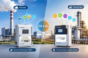
Depending on the fuel and selected accounting framework, the project may also need CH₄ or N₂O data. SO₂, NOₓ, CO and particulates can be relevant to treatment-system design and residual exhaust performance even when they are not part of the capture-rate calculation.
How Should Capture Performance Be Calculated?
Subtracting the outlet concentration from the inlet concentration can substantially overstate performance if the gas flows are different. Exhaust gas flow measurement must use time-aligned values and compatible reference conditions.
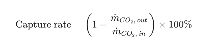
However, a complete evaluation may also compare:
- CO₂ entering the capture boundary.
- CO₂ remaining in the treated exhaust.
- CO₂ measured in the captured product.
- CO₂ released through vents or bypasses.
- Inventory changes in piping and tanks.
- Losses during storage and offloading.
- CO₂ generated by auxiliary energy consumption where required.
DNV’s framework distinguishes metrics including capture rate, captured quantity, atmospheric emissions and gross capture efficiency. These terms should be defined in the project specification rather than used interchangeably.
A good reconciliation test compares the removed mass from the exhaust with the measured captured product. A significant unexplained difference can indicate measurement error, vent losses, inventory changes or an incomplete boundary.
Which Analyzer Technologies Can Be Used?
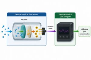
A single CO₂ analyzer does not provide all the information needed for performance verification. The analytical and flow instruments must be selected as one system.
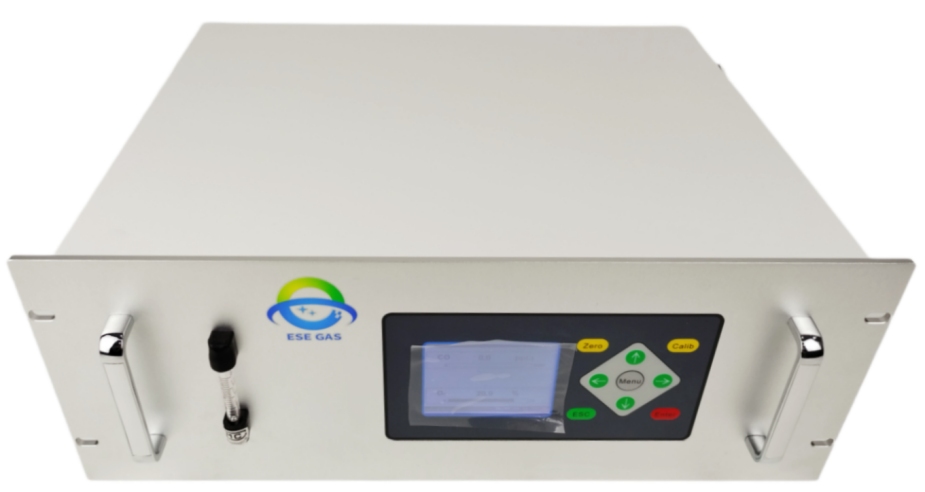
Possible technologies include:
- NDIR: Suitable for continuous CO₂ measurement over an appropriately configured range.
- FTIR: Useful when CO₂ and several infrared-active exhaust components must be measured together.
- Paramagnetic or electrochemical analysis: Options for oxygen.
- Dedicated CH₄ or N₂O measurement: Added where required by the fuel and accounting method.
- Moisture analysis: Supports wet-to-dry conversion or captured-product quality.
- Ultrasonic, differential-pressure or other flow measurement: Selected for the duct and captured-product conditions.
- Tank weighing, level or coriolis measurement: Supports stored-product inventory and transfer records.
- Laboratory analysis: Confirms captured-product composition when necessary.
ESEGAS can configure NDIR or FTIR-based CO₂ measurement with supporting O₂, moisture and gas-flow information. Before proposing a solution, we would confirm the required range, gas matrix, pressure, water content, response time and verification procedure.
What Additional Components May Need Monitoring?
Removing CO₂ can change the concentration or behaviour of other exhaust constituents. A capture installation should not reduce one emission while creating an uncontrolled release elsewhere.
Project-specific measurements may include:
- SO₂ where upstream sulfur removal affects the absorber.
- NO and NO₂ where they influence capture chemistry or final emissions.
- CO for combustion and exhaust assessment.
- CH₄ from engines using LNG or another methane-containing fuel.
- N₂O from relevant engine and after-treatment configurations.
- NH₃ where ammonia is used or can be released.
- Solvent vapours or degradation products from solvent-based systems.
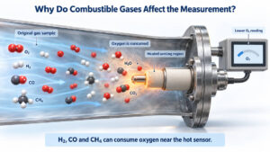
- O₂ and water for process balance and gas conditioning.
Solvent emission monitoring should be based on the actual capture medium. An amine system, membrane process and cryogenic process do not create the same target list or sampling requirements.
How Should Sampling Be Adapted to Shipboard Conditions?
A laboratory arrangement may become unreliable aboard a vessel because load changes, vibration, humidity and exhaust temperature are more severe. Long sampling lines can also delay the result until the engine has entered another operating condition.
The design should consider:
- Heated transport where condensation would bias the result.
- Corrosion-resistant wetted materials.
- Vibration-resistant probes, cabinets and connections.
- Sample pressure and flow regulation.
- Safe discharge of extracted gas.
- Automatic calibration-gas delivery.
- Protection from salt-laden ambient air.
- Redundant or maintainable critical components.
- Stable operation during vessel motion.
- Response testing through the complete sample path.
For wet exhaust, the system must state whether measurements are made on a wet or dry basis. Inlet and outlet results should not be compared until moisture and reference conditions are aligned.
How Should Dynamic Operating Conditions Be Handled?
A result obtained at one steady engine load does not describe a voyage containing manoeuvring, port operation, weather changes and capture-system interruptions. The measurement program must cover the operating envelope for which performance is claimed.
Data should be linked to:
- Engine load and fuel consumption.
- Fuel type and switching events.
- Capture-unit start and stop times.
- Absorber and regenerator conditions.
- Auxiliary power and heat demand.
- Bypass-valve position.
- Tank filling and venting.
- System alarms and maintenance.
- Ambient and seawater conditions where relevant.
- Voyage and operating mode.
Rapid load changes can create temporary imbalances because exhaust measurement, capture response and tank inventory do not react at the same speed. Appropriate averaging and inventory corrections are needed before these periods are interpreted.
How Should Captured CO₂ and Offloading Be Verified?
Measuring the exhaust is only half of the evidence chain. CO2 offloading quality and quantity must also be documented if the captured material is to be transferred into a transport, storage or utilisation chain.
The record may include:
- Captured-stream composition.
- Water content and other applicable impurities.
- Pressure, temperature and physical state.
- Tank inventory before and after transfer.
- Metered transfer quantity.
- Venting or return gas.
- Receiving facility identification.
- Sample and analysis records.
- Meter calibration status.
- Chain-of-custody documentation.
The required specification depends on the receiving infrastructure and final destination. We do not recommend applying a generic captured-CO₂ purity limit to every project.
What Data Quality Controls Are Required?
A high reported capture percentage is not defensible if the inlet analyzer, outlet flow meter and tank record use different timestamps or invalid operating periods.
A quality plan should include:
- Zero, span and multipoint checks.
- Flow-meter verification.
- Wet/dry and reference-condition controls.
- Response-time measurement.
- Clock synchronisation.
- Treatment of bypass and invalid data.
- Tank-inventory reconciliation.
- Calibration and maintenance records.
- Software and calculation version control.
- Uncertainty evaluation.
- Retention of original signals and status flags.
- Independent review or third-party verification.
Onboard carbon capture gas monitoring must connect exhaust measurement, captured-product accounting, storage and offloading into one traceable balance. At ESEGAS, we recommend defining that boundary before selecting the analyzers. A coordinated combination of CO₂, supporting gas channels, flow measurement and operating data provides a stronger basis for technical optimisation today and future regulatory verification.