



A battery recycler can meet its material-output target while still experiencing unstable furnace conditions, electrolyte releases or poor gas-treatment performance. If the plant monitors only recovered metals and final solids, changes inside shredding, drying and thermal-treatment stages may remain hidden until they cause an alarm, an odour complaint or an abnormal stack result.
Battery recycling off-gas monitoring should normally consider CO, CO₂, O₂, hydrogen fluoride and relevant organic vapours. H₂, HCl, SO₂, NOₓ and other components should be added according to battery chemistry, treatment method, fuel, reagents, air-pollution controls and permit requirements.
No universal gas list applies to every recycling facility. Mechanical separation, low-temperature electrolyte recovery, pyrolysis, hydrometallurgy and pyrometallurgy create different streams. The monitoring design should begin with the plant’s process flow and material inventory rather than a generic battery-analyzer specification.
Why Is Off-Gas Monitoring Becoming More Important?
Expanding recycling capacity without understanding lithium-ion battery recycling emissions can move contaminants from the solid feed into an uncontrolled gas or liquid stream. This is particularly important when black mass thermal treatment removes binders, electrolyte residues and organic material before metal recovery.
The EU Batteries Regulation requires permitted treatment facilities to use applicable best available techniques and establishes recycling-efficiency and material-recovery targets. In September 2026, the European Commission concluded that the existing targets remained appropriate.
These targets encourage efficient material recovery, but they do not prescribe one gas analyzer or prove that a facility meets its air-emission obligations. Operators must separately determine:
- Applicable industrial-emissions and waste permits.
- Stack and workplace requirements.
- Relevant best available techniques.
- Battery chemistries accepted by the plant.
- Treatment temperatures and atmospheres.
- Air-pollution-control equipment.
- Startup, shutdown and upset conditions.
- Reference and continuous measurement duties.
Monitoring should support these requirements without confusing material recovery with emissions compliance.
Which Process Stages Can Generate Off-Gas?
Measuring only the final stack can show what left the facility but may not explain which process caused the change. Different stages should first be mapped according to their materials and operating conditions.
Potential sources include:
- Battery opening and shredding: May release residual electrolyte vapours, dust and gas from damaged or charged cells.
- Drying or low-temperature treatment: Can evaporate electrolyte solvents and decompose electrolyte salts.
- Pyrolysis: Removes organics and binders under oxygen-limited conditions, producing combustible gases and vapours.
- Thermal oxidation: Treats organic off-gas and can produce conventional combustion pollutants.
- Pyrometallurgical processing: Produces high-temperature furnace gas, dust and chemistry-dependent acid gases.
- Hydrometallurgical operations: May generate acid mist or reagent-related vapours.
- Gas cleaning: Transfers contaminants into filters, scrubber liquids or sorbents.
- Material storage: Can release residual vapours or gas if damaged batteries remain reactive.
Each source should be linked to its normal route, treatment equipment, bypasses and final discharge point.
Which Gases and Compounds Should Be Considered?
Monitoring only CO and CO₂ can reveal combustion behaviour while missing corrosive fluorine compounds or unburned electrolyte material. The target list should reflect the feed and the process.
Possible measurements include:
| Component | Possible significance |
|---|---|
| CO | Incomplete oxidation, reducing furnace conditions and combustion safety |
| CO₂ | Carbon oxidation and process or combustion behaviour |
| O₂ | Air ingress, excess air, purge status and oxidizer control |
| HF | Fluorine-containing electrolyte or binder decomposition and acid-gas treatment |
| HCl | Chlorine-containing materials, contaminants or reagents |
| Total hydrocarbons or VOCs | Electrolyte solvents, organic binders and incomplete oxidation |
| H₂ | Reducing conditions, battery reaction or combustible-gas accumulation |
| CH₄ and light hydrocarbons | Pyrolysis and organic decomposition |
| SO₂ and NOₓ | Fuel, feed or combustion-related emissions where applicable |
| H₂O | Sample basis, condensation risk and process interpretation |
Research on low-temperature treatment has detected electrolyte solvents together with HF and POF₃ under the studied conditions. These findings show why HF gas monitoring and electrolyte vapor monitoring can be important, but they should not be treated as proof that every recycling line emits the same compounds at the same level.
Periodic laboratory analysis can identify additional organic and fluorinated species before the permanent online gas list is finalised.
Where Should Samples Be Collected?
A clean sample point downstream of several treatment stages cannot distinguish process generation from capture performance. Conversely, a raw-gas measurement alone does not establish the final atmospheric release.
A layered arrangement may include:
- Enclosure or extraction gas from shredding.
- Thermal-treatment reactor outlet.
- Pyrolysis condenser inlet and outlet.
- Thermal oxidizer inlet and outlet.
- Furnace outlet before gas cleaning.
- Scrubber or sorbent-system inlet and outlet.
- Final exhaust stack.
- Bypass, relief and emergency routes.
- Work areas requiring independent gas detection.
For pyrometallurgical off-gas, the probe must be positioned where dust loading, temperature and flow can be managed without losing representativeness. For electrolyte-recovery processes, measurements may also be needed around condensers to distinguish recovered solvent from material sent to destruction.
Which Analyzer Technologies Are Suitable?
A single detector cannot measure hydrogen, fluorinated acid gases, complex organics and oxygen with equal reliability. The analytical package may therefore combine several principles.
Possible methods include:
- FTIR: Simultaneously measures configured infrared-active gases such as HF, HCl, CO, CO₂, CH₄, water vapour and selected organic compounds.
- TDLAS: Provides selective measurement of configured gases such as HF or HCl where the range and matrix are suitable.
- FID: Measures total hydrocarbons or total organic carbon in an appropriate regulatory or process method.
- NDIR: Supports continuous CO, CO₂ and CH₄ measurement.
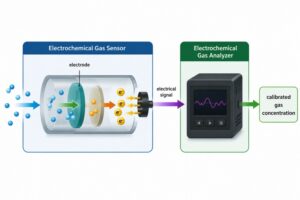
- Paramagnetic, zirconia or electrochemical analysis: Options for O₂.
- Thermal-conductivity detection: Can measure H₂ in a sufficiently defined background gas.
- GC or GC–MS: Supports detailed speciation and confirmation of organic compounds.
- Reference stack methods: Provide compliance measurements where required by the permit.
- Flow and dust measurement: Support mass-emission calculations and particulate control.
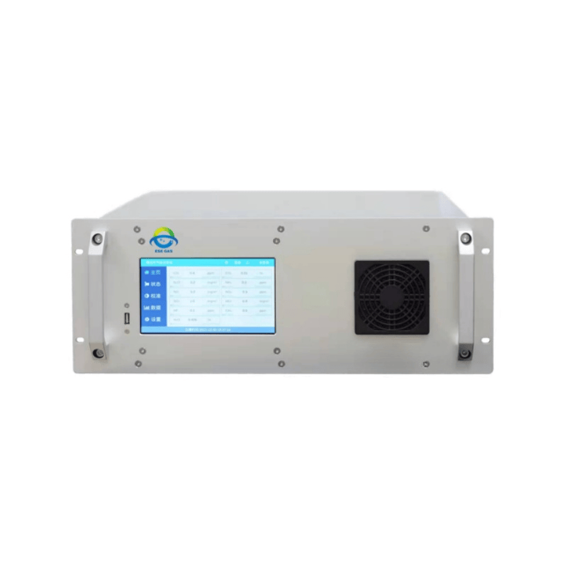
ESEGAS FTIR systems can be configured for several infrared-active components relevant to complex industrial exhaust. Inclusion in an FTIR library, however, does not automatically establish the required detection limit, lack of interference or regulatory acceptance. We would verify the actual gas matrix and method before specifying a battery recycling CEMS.
How Should Dust, Moisture and Condensable Material Be Managed?
An analyzer may report stable values while the sampling system is removing the compounds of interest. Electrolyte solvents can condense or adsorb, HF can be lost in moisture, and dust can rapidly block filters or contaminate optical cells.
The sample design should consider:
- Heated extraction and transport where condensation must be prevented.
- Materials compatible with acids and organic vapours.
- Filters that control particles without retaining target compounds.
- A short and controlled transport path.
- Stable sample pressure and flow.
- Automatic or accessible filter cleaning.
- Condensate handling when dry measurement is intended.
- Calibration-gas delivery through the sample path.
- Leak testing.
- Safe discharge or return of analyzed gas.
- Recovery testing for soluble and adsorptive compounds.
Hot-wet FTIR sampling can preserve water-soluble and condensable components when the complete path remains above the required temperature. A cold-dry system may simplify the analyzer environment, but the operator must demonstrate what is removed with the condensate and whether that loss is acceptable for the measurement objective.
How Can Gas-Treatment Performance Be Evaluated?
Comparing inlet and outlet concentrations alone can make a scrubber appear more effective when dilution air enters between the two points. Scrubber removal efficiency should use corresponding mass flows whenever gas volume changes materially.
The assessment may require:
- Inlet and outlet target-gas concentrations.
- Corresponding gas flows.
- Temperature, pressure and moisture.
- Reagent flow and pH.
- Differential pressure.
- Oxidizer temperature and oxygen.
- Filter or sorbent status.
- Battery feed rate and chemistry.
- Process operating mode.
- Bypass position.
- Analyzer validity flags.
The same principle applies to a thermal oxidizer. A lower organic concentration can result from destruction or dilution; CO, O₂, temperature and flow provide essential context.
Collected scrubber liquid and dust may also require laboratory analysis. Gas monitoring does not show whether fluorine or another contaminant was destroyed, captured or transferred to a secondary waste stream.
How Should Startup and Feed Changes Be Monitored?
An analyzer ranged only for steady production may saturate when a charged module enters the line, a furnace starts or an oxidizer loses temperature. These short events can be operationally important even if the daily average appears normal.
The monitoring plan should link gas data to:
- Battery chemistry and batch.
- State of charge where known.
- Feed rate.
- Shredder, kiln and furnace status.
- Inert-gas and combustion-air flow.
- Condenser conditions.
- Oxidizer temperature.
- Scrubber operation.
- Bypass events.
- Maintenance and cleaning.
- Fire or thermal-event alarms.
Multiple measurement ranges, dilution or separate high- and low-range channels may be needed. The system should record over-range events rather than silently replacing them with the analyzer’s maximum displayed value.
Why Must Process, Compliance and Safety Monitoring Remain Separate?
A stack analyzer cannot provide a fast local warning beside a shredder, and an area detector cannot quantify the facility’s atmospheric mass release. Using one instrument for all three functions creates technical gaps and a common point of failure.
| Monitoring layer | Main question | Typical arrangement |
|---|---|---|
| Process analysis | What is happening inside the treatment train? | Extractive multi-gas analyzer |
| Emissions compliance | What is released through the regulated discharge? | Approved CEMS or periodic reference testing |
| Safety detection | Is a hazardous local condition developing? | Independent fixed and portable detectors |
The systems may share data, but they should retain appropriate ranges, alarm logic, maintenance procedures and availability expectations. Critical safety functions should be evaluated independently by the responsible hazard team.
How Should Measurement Quality Be Controlled?
Complex off-gas can produce convincing numerical results even when spectral interference, filter loading or sample loss is present. Quality assurance must cover the complete measurement chain.
We recommend:
- Zero and span checks.
- Multipoint verification over normal and abnormal ranges.
- Interference assessment.
- Sample-line recovery tests.
- Leak and flow checks.
- Moisture-basis verification.
- Response and recovery-time testing.
- Periodic laboratory comparison.
- Flow-meter calibration.
- Time synchronisation with process data.
- Treatment of invalid and missing data.
- Retention of raw spectra, signals and maintenance records.
The target list should be reviewed when the facility accepts a new battery chemistry, changes its thermal process or modifies the gas-treatment train.
Battery recycling off-gas monitoring should connect feed chemistry, process control, gas treatment and final emissions without assuming that one analyzer can perform every task. At ESEGAS, we recommend mapping each gas route first, then combining appropriately conditioned FTIR, dedicated gas channels, flow information and independent safety detection. This provides more actionable process data while preserving a clear path to permit-specific validation.