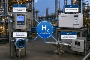


When an infrared gas analyzer starts showing unstable readings, slow response, or repeated calibration failures, the problem is rarely just a small inconvenience. A wrong gas concentration value can affect combustion control, process safety, emission monitoring, or environmental compliance. For operators, the real challenge is not only identifying that something is wrong, but knowing whether the issue comes from the analyzer itself, the sampling system, the gas condition, or daily maintenance habits. At ESEGAS, we understand that fast and accurate troubleshooting is essential for keeping gas analysis systems reliable in real industrial environments.
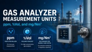
Common faults of an infrared gas analyzer include zero drift, span drift, unstable readings, slow response, low sample flow, optical contamination, condensation, calibration failure, pump or filter blockage, and communication errors. Most problems can be solved by checking the sample gas path, replacing blocked filters, verifying flow rate and pressure, removing moisture, cleaning the optical components, recalibrating the analyzer, and confirming power, signal, and communication connections.

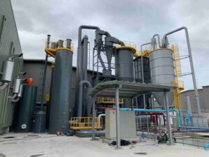
Although infrared gas analysis is based on a mature and stable measurement principle, field conditions are often complex. Dust, moisture, temperature changes, vibration, corrosive gases, and poor sample conditioning can all influence measurement accuracy. That is why ESEGAS does not view an analyzer as an isolated instrument. We focus on the complete gas analysis solution, including sampling, filtration, cooling, flow control, calibration, and long-term maintenance.
Why Do Infrared Gas Analyzers Show Zero Drift?
Zero drift is one of the most common problems in industrial gas measurement. At first, it may look like a small offset, but over time it can lead operators to trust an incorrect baseline. If the analyzer no longer returns to zero when clean zero gas is introduced, every measurement after that may become unreliable. For facilities using Infrared Gas Analyzers in emission monitoring, process control, or combustion optimization, this type of error should be handled quickly.
Zero drift usually means the analyzer’s reference point has shifted. The causes may come from the analyzer, the sample gas, or the operating environment.
Common causes include:
| Possible Cause | What It Means | Recommended Action |
|---|---|---|
| Impure zero gas | The zero gas contains trace target gas | Use certified high-purity zero gas |
| Residual gas in the sample cell | Previous sample gas remains inside the gas path | Purge the analyzer long enough before zero calibration |
| Optical cell contamination | Dust, oil mist, or moisture reduces infrared transmission | Inspect and clean the optical path if required |
| Temperature fluctuation | The analyzer environment changes too much | Keep the analyzer in a stable installation environment |
| Aging light source or detector | The infrared signal changes over time | Contact ESEGAS for component inspection or service |
| Incorrect calibration procedure | Zero calibration is performed before the system stabilizes | Allow sufficient warm-up and stable gas flow |
Our recommended troubleshooting sequence is simple: first confirm the zero gas quality, then check the gas flow rate, purge the system fully, and repeat zero calibration after the analyzer has reached a stable operating condition. If zero drift continues after these steps, the optical system or internal components may need professional inspection.
Why Are the Readings of Infrared Gas Analyzers Unstable?
Unstable readings can be frustrating because the analyzer may not show a clear fault alarm, yet the displayed concentration keeps jumping. This creates uncertainty for operators and makes it difficult to judge whether the process itself is changing or whether the measurement system is unreliable. In many cases, unstable readings in Infrared Gas Analyzers are caused by sample handling problems rather than a failure of the infrared measurement principle.
The first area to check is the sample gas condition. Infrared measurement requires a stable gas flow through the optical cell. If the flow rate, pressure, humidity, or sample composition changes suddenly, the reading may fluctuate.
Key causes and solutions include:
- Unstable sample flow
A fluctuating flow rate can cause unstable concentration values. Check the sampling pump, flowmeter, pressure regulator, valves, and tubing. The sample gas should enter the analyzer at a stable and recommended flow rate. - Leaks in the sampling line
A small leak can dilute the sample gas with ambient air. This is especially problematic when measuring low-concentration gases. Inspect all joints, fittings, connectors, and tubing for leakage. - Moisture in the sample gas
Water vapor or condensation can interfere with the infrared signal and cause unstable output. A properly selected sample gas cooler, drain system, and filter can reduce this risk. - Dust or particles entering the analyzer
Particulate contamination can affect the optical cell and block filters. Replace filter elements regularly and make sure the sampling probe is suitable for the gas condition. - Electrical or signal interference
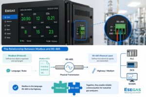
Poor grounding, unstable power supply, or nearby high-power equipment may affect signal transmission. Check the power connection, grounding, analog output wiring, and communication cables.
At ESEGAS, we usually suggest checking the sampling system before adjusting analyzer parameters. A stable sample gas path often solves most unstable reading problems.
What Causes Slow Response Time in Infrared Gas Analyzers?
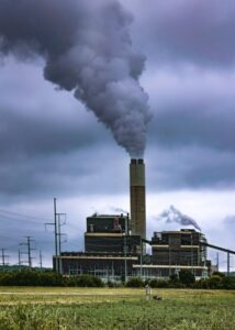
Slow response can be dangerous in applications where operators need real-time feedback. When the process gas concentration changes but the analyzer responds too late, the control system may react based on old information. This is especially important in continuous emission monitoring, industrial safety, furnace control, and process optimization. For Infrared Gas Analyzers, response time depends not only on the analyzer itself but also on the entire sampling system.
The most common reason for slow response is delayed sample gas delivery. Even a high-performance analyzer cannot respond quickly if the sample gas reaches it too slowly.
Common causes include:
- Blocked sample filter: A dirty filter restricts gas flow and increases delay.
- Long sampling tube: The longer the sample line, the longer the transport time.
- Weak sampling pump: A pump with reduced performance cannot maintain proper flow.
- Condensation in the line: Liquid water can partially block the gas path.
- Narrow or bent tubing: Physical restrictions reduce flow speed.
- Contaminated gas cell: Deposits inside the optical cell can slow signal stabilization.
To solve slow response, start by checking the flow rate at the analyzer inlet. Then inspect the filter, sample line, pump, and drain system. If the sample line is too long, consider optimizing the sampling layout. In high-dust or high-moisture applications, correct sample pretreatment is often the most effective way to maintain fast response.
Why Do Infrared Gas Analyzers Fail Calibration?
Calibration failure can interrupt normal operation and create doubt about the reliability of the analyzer. The problem becomes more serious when the analyzer repeatedly fails zero or span calibration even after standard gas is introduced. For operators using Infrared Gas Analyzers in regulated monitoring or quality control, calibration failure should be treated as a system-level issue, not just an instrument setting problem.
Calibration failure usually comes from one of four areas: gas quality, flow condition, analyzer stability, or optical contamination.
Check the following points:
- Is the calibration gas correct?
Confirm the gas type, concentration, balance gas, certificate validity, and cylinder pressure. The span gas concentration should match the analyzer range and application requirement. - Is the gas flow stable?
Too much or too little calibration gas flow can affect the result. Use the recommended flow range and avoid pressure shocks during calibration. - Has the analyzer fully warmed up?
Infrared analyzers require stable internal temperature and signal conditions. Calibration should not be performed immediately after power-on unless the instrument has completed its warm-up period. - Is the sample path clean?
Residual sample gas, moisture, or contamination may remain in the gas path. Purge the analyzer before calibration. - Is the optical path contaminated?
If the detector receives a weak or unstable infrared signal, calibration may fail. In this case, cleaning or service may be required.
Our ESEGAS recommendation is to record every calibration result, including gas concentration, flow rate, time, and environmental condition. A calibration history helps identify whether the problem is random, progressive, or related to a specific operating condition.
How Do Moisture and Condensation Affect Infrared Gas Analyzers?
Moisture is one of the most common enemies of accurate gas analysis. A small amount of water vapor may be acceptable in some applications, but condensation inside the sampling line or analyzer can create serious problems. Once liquid water enters the gas path, it can block flow, contaminate filters, damage components, and interfere with infrared absorption. For Infrared Gas Analyzers, moisture control is a key part of measurement reliability.
Condensation usually occurs when hot, wet sample gas cools down before reaching the analyzer. This is common in flue gas monitoring, combustion exhaust, biogas, chemical processes, and other high-humidity applications.
Moisture can cause:
- Unstable readings
- Slow response
- Low sample flow
- Corrosion of metal components
- Filter blockage
- Optical window contamination
- Calibration errors
- Unexpected alarms or shutdowns
The best solution is prevention. A suitable sample conditioning system should remove particles and control moisture before the gas enters the analyzer. Depending on the application, this may include a heated sampling probe, heated sample line, gas cooler, automatic drain, moisture trap, and fine filter.
At ESEGAS, we pay close attention to sample pretreatment because the analyzer’s performance depends heavily on the quality of the gas sample it receives. A well-designed conditioning system can greatly reduce maintenance frequency and improve long-term stability.
What Should You Check When the Sample Flow Is Too Low?
Low sample flow is a simple fault to observe but not always simple to locate. If the analyzer receives insufficient gas, the reading may become delayed, unstable, or lower than the actual process concentration. In some systems, low flow may also trigger an alarm or stop the measurement. For Infrared Gas Analyzers, stable flow is essential because the optical cell must be filled with representative sample gas.
A low-flow fault should be checked from the sampling point to the analyzer outlet.
Recommended inspection order:
- Sampling probe
Check whether the probe is blocked by dust, tar, moisture, or process deposits. - Primary filter
Replace the filter element if it is dirty or saturated. - Sample line
Look for bends, crushed tubing, leaks, or liquid accumulation. - Sample pump
Confirm whether the pump is running normally and providing sufficient suction. - Flowmeter or rotameter
Make sure the flowmeter is not blocked or damaged. - Valves and fittings
Confirm that all valves are open and all fittings are properly connected. - Exhaust line
A blocked outlet can also reduce flow through the system.
In many cases, replacing a clogged filter or removing condensed liquid restores normal flow. However, if low flow appears frequently, the sampling design may need improvement. A system that constantly blocks is usually not matched well to the dust, moisture, or temperature conditions of the application.
Can Optical Contamination Cause Measurement Errors in Infrared Gas Analyzers?
Yes. Optical contamination is one of the most direct causes of measurement error. Infrared measurement depends on the amount of infrared light absorbed by the target gas. If dust, oil mist, water droplets, or chemical deposits cover the optical window or gas cell, the detector may receive a weaker signal. This can cause drift, noise, calibration failure, or incorrect concentration values. For Infrared Gas Analyzers, keeping the optical path clean is essential.
Typical signs of optical contamination include:
- Gradual signal drift
- Increasing calibration frequency
- Poor repeatability
- Low infrared signal strength
- Slow stabilization after gas change
- Calibration failure even with correct standard gas
Before cleaning optical components, operators should follow the manufacturer’s maintenance procedure. Incorrect cleaning methods may scratch the optical window or damage sealing parts. In many cases, it is safer to contact ESEGAS technical support for guidance, especially when the analyzer is used in corrosive, toxic, or high-value process applications.
To reduce optical contamination, we recommend improving filtration and moisture removal before the gas enters the analyzer. Preventing contamination is always better than frequently opening and cleaning the optical cell.
How Can Operators Prevent Repeated Faults in Infrared Gas Analyzers?
Repeated analyzer faults often indicate that the maintenance plan is reactive rather than preventive. When operators only respond after alarms occur, the same problems may return again and again. This increases downtime, spare parts consumption, and uncertainty in measurement data. With Infrared Gas Analyzers, a structured maintenance routine can prevent most common failures.
A practical preventive maintenance plan should include:
| Maintenance Item | Suggested Purpose |
|---|---|
| Check sample flow daily | Confirm that the analyzer receives enough gas |
| Inspect filters regularly | Prevent dust and particles from entering the analyzer |
| Drain condensate | Avoid water entering the gas path |
| Check pump operation | Maintain stable sampling performance |
| Verify zero and span periodically | Keep measurement accuracy under control |
| Inspect tubing and fittings | Prevent leakage and blockage |
| Record alarms and calibration data | Identify fault trends early |
| Keep the analyzer environment stable | Reduce temperature and electrical interference |
For demanding industrial applications, we recommend keeping a maintenance log. Record zero values, span values, flow rates, filter replacement dates, and fault alarms. Over time, this data helps operators predict problems before they affect production or compliance.
ESEGAS also encourages users to treat the gas analyzer and sample conditioning system as one complete measurement chain. When the full chain is maintained properly, the analyzer can perform more accurately and reliably.
When Should You Repair, Replace, or Upgrade Infrared Gas Analyzers?
Not every fault means the analyzer must be replaced. Many issues can be solved by changing filters, repairing the sampling pump, cleaning the gas path, replacing worn components, or recalibrating the instrument. However, if faults become frequent or the analyzer no longer meets the process requirement, repair alone may not be the best solution. For older Infrared Gas Analyzers, replacement or system upgrade may reduce long-term operating cost.
Repair is usually suitable when:
- The analyzer is generally stable but has a clear component fault
- The optical system is still in good condition
- Spare parts are available
- The measurement range and gas components still match the application
- The fault is caused by sampling accessories rather than the analyzer core
Replacement or upgrade may be better when:
- Drift occurs frequently after calibration
- The analyzer response is too slow for the process
- Maintenance cost keeps increasing
- The application gas composition has changed
- The analyzer cannot connect with modern control or data systems
- The optical or electronic components are seriously aged
- The existing sample conditioning system is not suitable for current conditions
At ESEGAS, we help users evaluate the complete application before recommending repair or replacement. Our goal is not only to provide an analyzer, but to deliver a gas analysis solution that matches the real working conditions, target gas, measurement range, sample temperature, humidity, dust level, and communication requirements.
Conclusion
Common faults of an infrared gas analyzer are usually related to zero drift, unstable readings, slow response, low sample flow, calibration failure, moisture, optical contamination, or signal connection problems. In most cases, the root cause is not limited to the analyzer itself. The sampling system, gas conditioning method, calibration procedure, and maintenance routine all play important roles in measurement stability.
At ESEGAS, we design and support gas analysis solutions with long-term industrial reliability in mind. By checking the sample gas path, controlling moisture and dust, maintaining stable flow, using correct calibration gas, and protecting the optical system, operators can reduce repeated failures and achieve more accurate gas concentration measurement. For users working with Infrared Gas Analyzers in demanding industrial environments, a complete and well-maintained gas analysis system is the key to safer operation, better process control, and more dependable data.