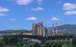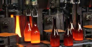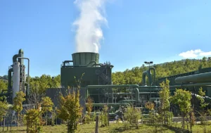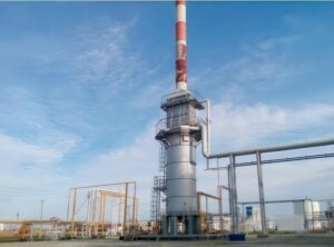


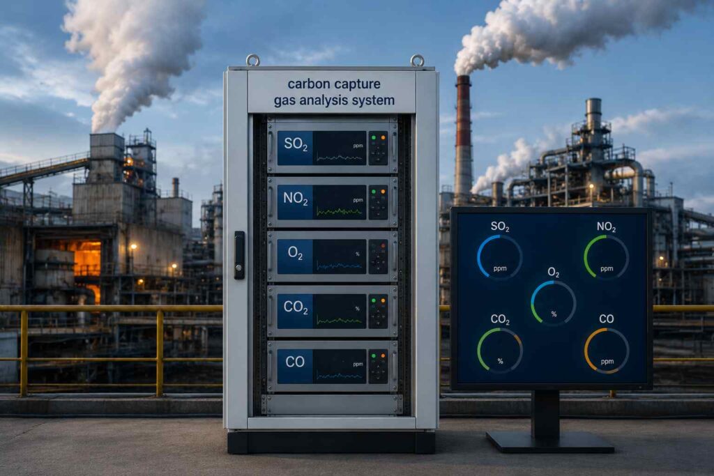
A European glass plant recently commissioned a compact carbon capture gas analysis system for carbon capture project. The project focused on two goals. First, the customer wanted to understand the dynamic behavior of the glass melting process. Second, the plant needed stable online gas monitoring of CO₂ purity before downstream carbon capture handling.
A complete carbon capture system usually includes three core sections:
- CO₂ capture
- CO₂ transportation
- CO₂ utilization or storage
Among them, the capture stage is the most sensitive part of the entire process. This is where the carbon capture gas analysis system plays a critical role.
Instead of discussing carbon capture only from a theoretical perspective, this article will introduce a real customized carbon capture gas analysis system used in an industrial glass plant.
Why Does the Glass Industry Need a Carbon Capture Gas Analysis System?
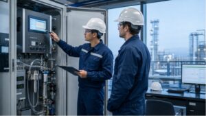
We design the carbon capture gas analysis system as an integrated online monitoring system. Moreover, it can continuously measure flue gas composition before, during, and after the carbon capture process. It helps operators in glass plant understand real-time process conditions inside the flue gas stream and maintain stable CO₂ capture performance under changing industrial loads.
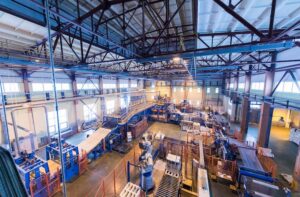
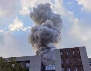
Glass manufacturing creates high-temperature flue gas with fluctuating gas concentrations. Furnace temperature, fuel quality, combustion efficiency, airflow, and production rate can all affect the flue gas condition. Without continuous gas monitoring, operators cannot accurately evaluate capture efficiency, solvent performance, or CO₂ purity. Traditional manual sampling cannot provide continuous process visibility. Operators often miss fast concentration changes inside the flue gas stream. A dedicated online gas analysis system solves this problem through continuous measurement and automated sampling.
In practical industrial operation, the online gas analysis system does much more than simply measure CO₂. Also, it helps operators:
- optimize combustion conditions
- reduce solvent degradation
- detect process instability
- protect downstream purification equipment
- improve carbon capture efficiency
- maintain long-term system reliability
Which Gas Components Need Continuous Monitoring in a Carbon Capture Gas Analysis System?
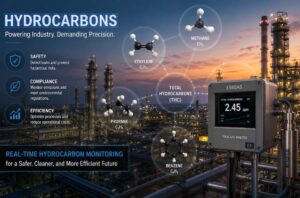
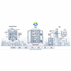
Different gas components directly influence the stability and efficiency of the carbon capture process. Each gas requires a suitable measurement technology based on concentration range, process conditions, and interference resistance. As an illustration, glass furnaces release large volumes of CO₂, CO, SO₂, and NOx during combustion. These gases directly affect carbon capture efficiency and downstream purification quality.
Carbon Capture Gas Analysis System Measured Components & Technologies
| Gas Component | Measuring Range | Technology | Why It Matters |
| O₂ | 0–1000 ppm | ECD | Determines capture efficiency and purity |
| CO₂ | 0–100% | NDIR | Measures CO₂ concentration and purity |
| CO | 0–100 ppm | NDIR | Reflects incomplete combustion |
| SO₂ | 0–50 ppm | UV-DOAS | Can damage carbon capture solvents |
| NO₂ | 0–100 ppm | UV-DOAS | Impacts downstream purification systems |
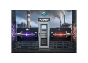
NDIR technology is widely used for CO₂ and CO measurement because of its high stability and strong resistance to industrial interference. Meanwhile, It performs particularly well in high-moisture and high-CO₂ environments.
UV-DOAS technology offers excellent low-level SO₂ and NO₂ detection capability. Also, it provides strong immunity against dust and moisture interference in flue gas applications.
For ultra-low oxygen measurement, the system uses ECD technology to monitor combustion conditions and process balance with high sensitivity.
Together, these technologies create a stable Carbon Capture Gas Analysis System for long-term carbon capture operation.
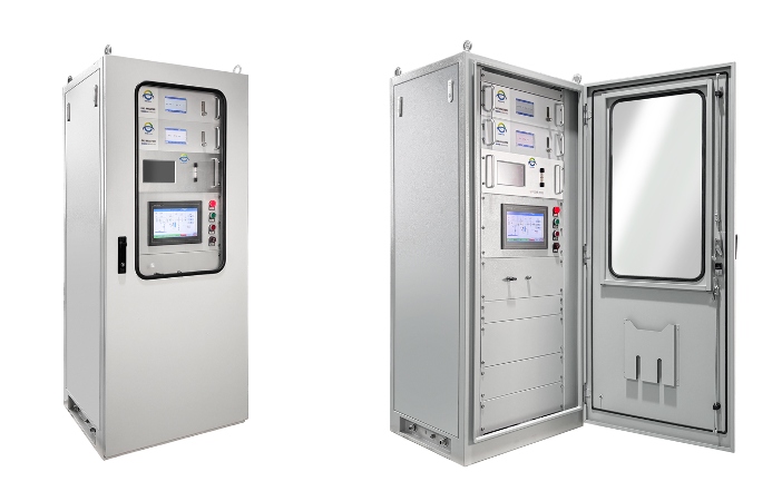
What Are the Main Components of a Carbon Capture Gas Analysis System?
The customized carbon capture gas analysis system used in the glass plant consists of four major sections. Each section performs a specific task to ensure stable online gas monitoring under demanding industrial conditions.
1. Sampling Unit
The sampling unit is the starting point of the entire system.
It includes:
- pre-embedded welded sampling pipe section
- ball valve
- terminal fittings
- sample transport pipeline
One side of the sampling section is welded directly onto the process flue gas pipeline. The other side connects to the heated sampling line leading to the analyzer cabinet.
On the one hand, this design helps maintain representative gas extraction while minimizing leakage risk and sample loss during transport. On the other hand, in high-temperature carbon capture applications, stable sampling is critical because flue gas conditions can fluctuate rapidly during furnace operation.
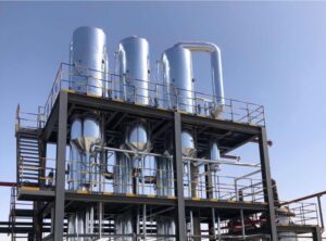
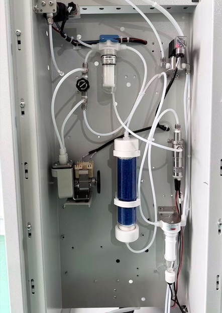
2. Sample Gas Conditioning Unit
Raw flue gas is unsuitable for direct analyzer measurement.
To ensure stable online monitoring, the system integrates:
- two-stage condenser system
- gas filtration unit
- Bühler sampling pump
The sample gas first enters the condensers, where moisture and condensate are removed. Then, the gas passes through multiple filtration stages to eliminate particulate matter before entering the gas analyzers.
This conditioning process protects sensitive optical components and improves gas analyzer stability during long-term operation. Without proper gas conditioning, issues such as condensation, dust contamination, and optical chamber fouling can quickly affect measurement accuracy.
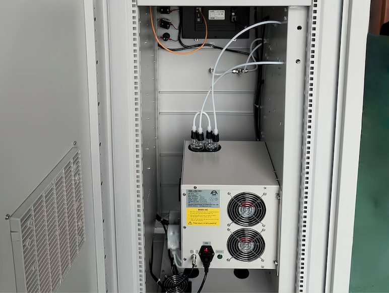
3. Automatic Control Unit
The entire gas analysis system operates automatically through a PLC-based control platform.
Key components include:
- Siemens PLC control system
- intermediate relays
- solenoid valves installed at each gas control point
The PLC automatically manages gas sampling, valve switching, system status control, and signal communication.
This automatic design reduces manual operation and improves overall system consistency. Also, it allows easier integration into modern industrial control systems and centralized monitoring platforms. For large industrial plants, automatic operation helps maintain stable measurement performance around the clock.
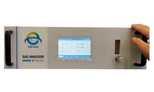
4. Gas Analysis & Data Output Unit
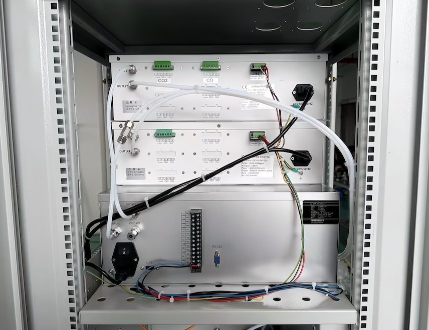
The gas analysis and data output section is the central part of the carbon capture gas analysis system. The system uses three online flue gas analyzers with: high stability, low maintenance requirements, continuous online measurement capability, and user-friendly operation interface.
The gas analyzers continuously monitor the key gas components inside the glass furnace flue gas stream and transmit the measurement data to the plant control system in real time.
The gas analyzers are equipped with:
- 4–20 mA analog output
- RS485 serial communication
- RS232 communication interface
- LCD display and full-touch screen
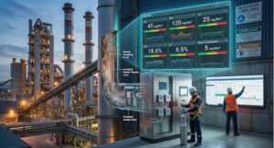
Through shielded signal cables, gas concentration data can be transmitted directly to the customer’s central control room for: centralized monitoring, process optimization, trend analysis, alarm management, and historical data recording. This allows operators to respond quickly to process changes and maintain stable carbon capture operation over long production cycles.
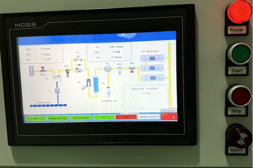
How Does the Carbon Capture Gas Analysis System Workflow Operate?
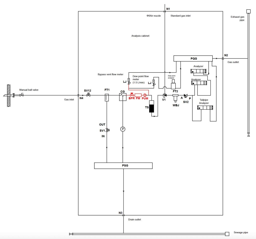
| NO. | Symbol | Name | Function |
| 1 | SV1 | Two-way solenoid valve (normally closed) | Filter drain |
| 2 | SV2 | Two-position three-way solenoid valve | Protection/venting solenoid valve |
| 3 | SV3 | Two-way solenoid valve (normally closed) | Atmospheric communication solenoid valve |
| 4 | V1 | Manual two-position three-way valve | Sampling/calibration switching |
| 5 | FT1 | Primary filter | First level filter |
| 6 | FT2 | Precision filter | Secondary filter |
| 7 | WBJ | Humidity alarm | Humidity alarm |
| 8 | PUM | Sampling pump | Sample gas extraction |
| 9 | P | Peristaltic pump | Condenser drain |
| 10 | LJ | Flow meter | Bypass shorting |
| 11 | CG | Condenser | Sample gas condensation |
| 12 | TS | Color changing silicone jar | Remove water from sample gas |
| 13 | PSG | Drainpipe | Drainage |
| 14 | PQG | Exhaust gas pipe | Exhaust |
| 15 | SV11 | Two-way solenoid valve (normally closed) | Pass in compressed air |
| 16 | SV12 | Two-way solenoid valve (normally closed) | Sampling |
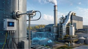
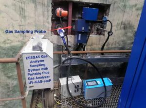
The working principle of a carbon capture gas analysis system starts with reliable flue gas extraction. A sampling probe installed directly on the process pipeline continuously extracts flue gas from the furnace or stack. The gas then travels through the heated sampling line into the gas analyzer cabinet. However, raw flue gas cannot enter the gas analyzers directly. Industrial flue gas usually contains high moisture, condensate, dust, fine particles, and corrosive components.
These contaminants can damage sensors, contaminate optical chambers, and reduce measurement stability. To solve this problem, the system performs several stages of gas conditioning before analysis.
Inside the analyzer cabinet, the gas passes through the following process:
1. Two-Stage Condensation
The first stage removes moisture and liquid condensate from the sample gas. This step protects downstream components and stabilizes gas conditions.
2. Primary Filtration
Larger dust particles and impurities are removed to prevent contamination inside the gas path.
3. Sample Gas Pumping
A Bühler sampling pump provides stable gas transport and maintains consistent sample flow to the analyzers.
4. Precision Filtration
A high-precision filter removes particles larger than 1 μm before the gas enters the analyzers.
5. Online Gas Analysis
The fully conditioned gas finally enters the online flue gas analyzers for continuous measurement.
This complete conditioning process significantly improves long-term measurement reliability while reducing maintenance frequency in harsh industrial environments.
In real carbon capture projects, stable sample conditioning is often just as important as the gas analyzer itself. Many unstable readings are not caused by sensor failure, but by moisture, dust buildup, or improper gas treatment inside the sampling system.
Conclusion
The customized carbon capture gas analysis system introduced in this article shows how online gas analysis can support carbon capture projects under harsh industrial conditions, including high temperature, moisture, and dust-loaded flue gas environments. From gas sampling and conditioning to NDIR, UV-DOAS, ECD, PLC automation, and centralized data output, every part of the system directly affects measurement accuracy and process reliability.
If you are planning a carbon capture project or upgrading an existing CCUS facility, now is the right time to evaluate your current gas monitoring capability. Outdated gas analyzers, unstable sampling systems, or incomplete gas measurement can limit overall capture performance.
Better gas analysis leads to better carbon capture results.
FAQs:
1: What is a carbon capture gas analysis system?
A carbon capture gas analysis system is an online monitoring system used to continuously measure flue gas composition during the carbon capture process. It typically analyzes gases such as CO₂, O₂, CO, SO₂, and NOx to help operators monitor capture efficiency, optimize process conditions, and ensure stable system operation. The system usually includes gas sampling, sample conditioning, analyzers, PLC control, and data communication units.
2: Why is CO₂ purity monitoring important in carbon capture?
CO₂ purity directly affects pipeline safety, solvent performance, downstream utilization, and regulatory compliance. Impurities such as SOx, NOx, moisture, hydrocarbons, or oxygen can cause corrosion, reduce storage quality, and damage equipment. Continuous CO₂ purity monitoring helps operators maintain stable capture performance and meet transportation or storage specifications.
3: Which gas analyzer technologies are used in carbon capture systems?
Several analyzer technologies are commonly used in carbon capture applications:
- NDIR for CO₂ and CO measurement
- UV-DOAS for SO₂ and NO₂ monitoring
- ECD for low-level O₂ analysis
- FTIR for multi-component impurity monitoring
- Gas Chromatography (GC) for detailed gas composition analysis
The selected technology depends on gas composition, measurement range, response time, and process conditions.
4: What gases should be monitored in carbon capture applications?
The most commonly monitored gases include:
- CO₂ for capture efficiency and purity
- O₂ for combustion optimization and leak detection
- CO for combustion performance
- SO₂ and NOx for solvent protection and emissions control
- Moisture and trace impurities for pipeline safety and corrosion prevention
Different industries may also monitor CH₄, H₂S, NH₃, or hydrocarbons depending on the process design.
5: Can carbon capture gas analysis systems operate in high-temperature environments?
Yes. Industrial carbon capture gas analysis systems are designed for harsh operating conditions, including high-temperature flue gas applications. The system usually uses heated sampling probes, condensers, filters, and sample conditioning units to reduce gas temperature and remove moisture or dust before the gas enters the analyzer. Proper sample conditioning is critical for stable long-term measurement.
6: Why are SO₂ and NO₂ monitoring important in carbon capture processes?
SO₂ and NO₂ can significantly affect carbon capture efficiency. These acidic gases may react with capture solvents, increase corrosion risk, reduce absorber performance, and contaminate captured CO₂ streams. Continuous monitoring helps operators protect downstream equipment, maintain solvent stability, and improve overall process reliability.