



Ammonia cracking plants may maintain the expected reactor temperature while producing gas that still contains excessive ammonia or does not meet the downstream hydrogen requirement. Catalyst condition, feed variation, purification performance and air leakage can all change the outlet. Continuous gas information allows operators to identify these changes before they affect equipment, safety or product use.
An ammonia cracking system should normally monitor hydrogen and residual ammonia, with oxygen and moisture added where they are relevant to safety, purification or product quality. Nitrogen may be measured directly or determined using an approved analytical balance, depending on the required accuracy and application.

The best configuration depends on where the measurement is taken. Raw reactor gas, cooled gas, purified hydrogen and vent gas have different compositions and analytical ranges, so one sample point should not be expected to answer every operational question.
What Does the Cracking Reaction Tell Us About the Gas List?
Monitoring only reactor temperature assumes that chemical equilibrium, catalyst activity and residence time remain unchanged. Residual ammonia monitoring provides direct evidence of breakthrough that a temperature sensor alone cannot reveal.
This chemistry makes the following components important:
| Component | Why it may be monitored |
|---|---|
| H₂ | Main product and an indicator of conversion and purification performance |
| NH₃ | Detects incomplete conversion or breakthrough |
| N₂ | Supports composition balance and assessment of the raw product gas |
| O₂ | Indicates possible air ingress, purge problems or unsafe conditions |
| H₂O | Supports dryer control and product-quality assessment |
| Other impurities | Selected according to feed quality, catalyst, heating method and downstream use |
Ammonia conversion efficiency should be evaluated from representative inlet and outlet information rather than from hydrogen concentration alone. Dilution, recycle gas or nitrogen introduced elsewhere can change the percentage of hydrogen without changing the amount of ammonia converted.
Where Should Gas Measurements Be Taken?
Installing an analyzer only at the final product line can show that a specification has been missed, but it may not show whether the reactor, cooler or purifier caused the problem. A layered measurement arrangement makes fault diagnosis faster.
Useful locations include:
- Feed line: Confirm ammonia delivery conditions where direct measurement is necessary.
- Reactor outlet: Evaluate cracked gas composition and residual NH₃ before purification.
- After cooling or separation: Check the effect of condensation and intermediate treatment.
- Purifier outlet: Perform hydrogen purity measurement and verify limiting contaminants.
- Recycle or fuel line: Support burner and heat-integration control.
- Vent or relief system: Detect NH₃ or H₂ releases associated with abnormal operation.
- Equipment area: Provide separate safety detection for leaks and gas accumulation.
Process analysis and area safety detection serve different purposes. A process analyzer measures a controlled sample for composition, while fixed safety detectors should provide independent alarms at locations determined by the hazard assessment.
Which Technologies Fit Each Component?
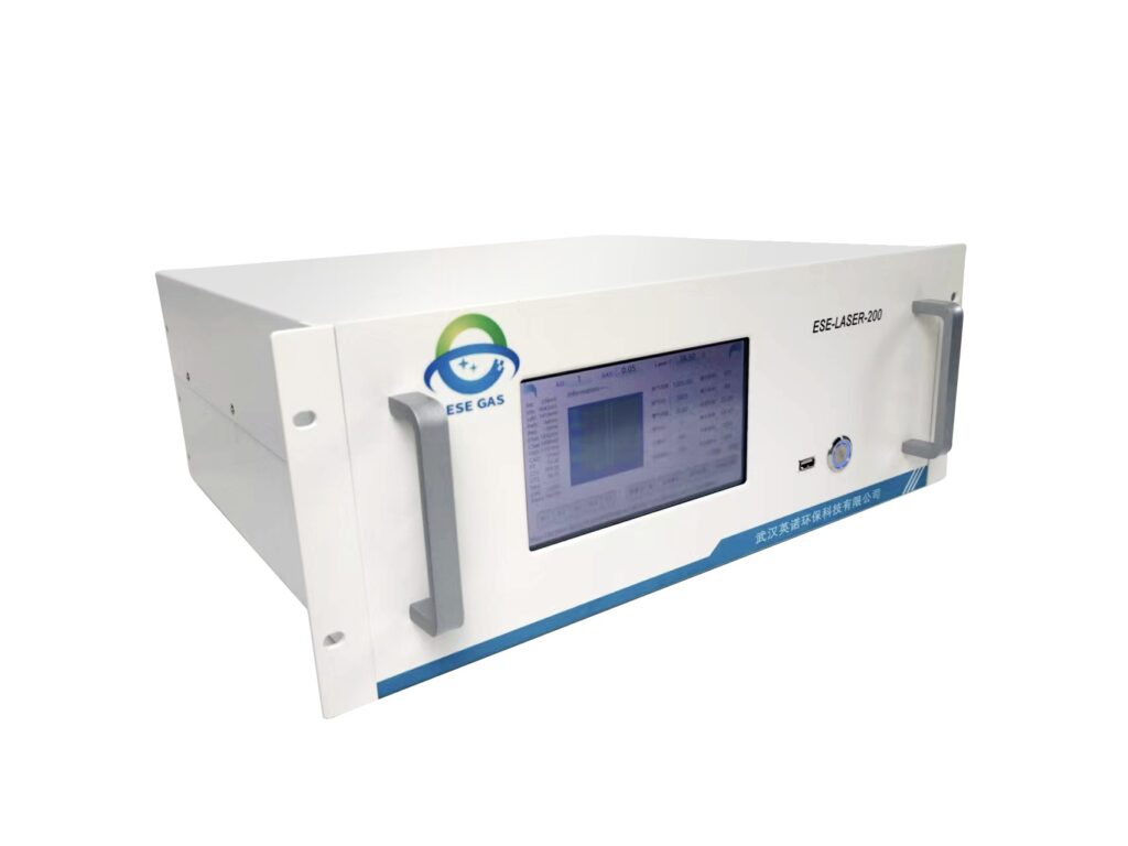
No single optical principle measures NH₃, H₂, N₂, O₂ and moisture equally well. Combining measurement channels usually provides a more defensible result.
Possible technologies include:
- TDLAS: Provides selective NH₃ measurement when the selected absorption line, pressure, temperature and expected range are suitable.
- FTIR: Can measure NH₃ and other infrared-active components simultaneously when calibrations and interferences are validated.
- Thermal conductivity detection: Commonly used for bulk H₂ analysis in a defined background-gas matrix.
- Process gas chromatography: Separates H₂, N₂ and other components for detailed composition verification.
- Paramagnetic, zirconia or electrochemical methods: Options for O₂ measurement depending on the range and sample conditions.
- Moisture analysis: May use chilled-mirror, capacitive, electrolytic or optical methods according to the required moisture range.
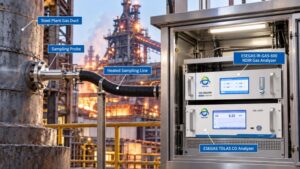
At ESEGAS, we define the measurement duty before selecting a channel. A hydrogen analyzer intended for raw cracked gas may require a different calibration and background compensation from an analyzer installed after purification.
How Should the Sample System Handle Ammonia and Moisture?
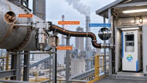
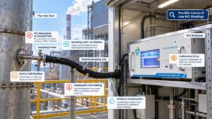
An analyzer can be correctly calibrated yet report a low NH₃ value if ammonia is adsorbed or dissolved before reaching the measurement cell. Cooling wet gas can also create condensate that changes sample composition and damages downstream components.
The sample-conditioning design should consider:
- A short, low-volume sampling path.
- Wetted materials compatible with ammonia, hydrogen and moisture.
- A heated sample line where condensation or adsorption would bias the result.
- Filtration that protects the analyzer without retaining target gas.
- Controlled sample pressure and flow.
- Safe venting or return of the analyzed gas.
- Separation of condensate only when the analytical basis permits it.
- Purging before maintenance or calibration.
- Leak testing appropriate for a hydrogen-containing stream.
- Recovery testing through the complete sampling path.
If a dry measurement is required, the operator should document which compounds could be lost during moisture removal. If a hot-wet method is used, the analyzer and calibration model must account for water vapour.
How Can Gas Data Improve Reactor Control?
Waiting for an off-spec laboratory result delays corrective action and can allow a large volume of unsuitable gas to reach the purifier or storage system. Time-resolved data can identify the beginning of a conversion problem.
Operators can use the trends to:
- Detect declining catalyst activity.
- Compare conversion with reactor temperature and feed rate.
- Adjust residence time or thermal input.
- Identify unstable feed delivery.
- Detect purifier breakthrough.
- Verify purge completion during startup and shutdown.
- Support oxygen ingress detection.
- Correlate maintenance with performance recovery.
A rising NH₃ trend accompanied by changing H₂ can indicate conversion deterioration. A sudden O₂ increase may instead point to leakage or sample dilution. Interpretation should therefore combine several gas channels with pressure, temperature, flow and valve status.
How Should Product Requirements Affect the Analyzer Design?
A configuration suitable for burner fuel may not be sufficient for hydrogen supplied to a fuel cell or another purity-sensitive process. The intended use determines which impurities matter and how low they must be measured.
Before defining the system, operators should confirm:
- The applicable product specification.
- Maximum permitted residual NH₃.
- Required H₂, N₂ and moisture information.
- Expected raw and purified gas ranges.
- Normal and abnormal pressures.
- Whether the sample contains condensable material.
- Required alarm and control response.
- Validation and laboratory comparison procedures.
A wide-range process measurement and a trace-quality measurement may require separate channels. Switching one analyzer between very high and very low concentrations can create long recovery periods and increase contamination risk.
How Can Response Time and Data Quality Be Verified?
A fast analyzer cannot provide fast plant information if the sampling line has excessive volume or insufficient flow. Poor analyzer response time can make breakthrough appear later than it actually occurred.
The commissioning program should include:
- Zero and span verification.
- Challenge testing through the full sample line.
- Response and recovery measurements.
- Calibration in a representative background gas.
- Checks at normal and elevated NH₃ levels.
- Pressure and flow sensitivity tests.
- Time synchronization with reactor and purifier data.
- Comparison with an independent analytical method.
- Documentation of drift, uncertainty and maintenance intervals.
Calibration gas should be delivered through as much of the normal sampling path as practicable. This checks valves, tubing, filters and conditioning components as well as the analyzer.
What Should Be Confirmed Before Selecting the System?
Ordering a generic “ammonia cracker analyzer” without defining its location can produce unsuitable ranges and sampling materials. A short application review prevents most of these design errors.
At ESEGAS, we recommend confirming:
- Measurement point and process objective.
- Minimum and maximum concentration of every target gas.
- Background-gas composition.
- Temperature, pressure, moisture and particulate content.
- Required response time.
- Normal, startup and shutdown conditions.
- Purification technology.
- Alarm and control interfaces.
- Calibration access and validation method.
- Hazardous-area and installation requirements.
Reliable ammonia cracking gas analysis should connect reactor performance, purification, product quality and safety without confusing their different measurement needs. At ESEGAS, we combine suitable NH₃, H₂, O₂ and moisture technologies around the actual sample conditions, helping operators detect incomplete conversion, purifier breakthrough and abnormal operation with data they can interpret and act on.