

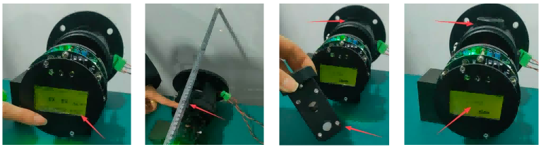
- Preparation
First, make sure the dust monitor is powered on and fully warmed up. Confirm the current optical path is set to 0.5m, which is the calibration baseline. Also prepare your calibration block set to a 2000 Lv value at 0.5m as your reference standard.
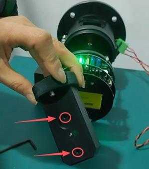
- Key Adjustment Screws
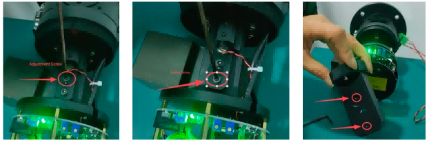
Before you begin, locate the main mechanical controls:
- Adjustment screw — changes the laser’s optical angle to tune signal level.
- Fixation screw — locks the adjusted optical position in place.
- Calibration block rear screws — tweak the optical window angle on the calibration block itself.
- Zero Signal Setup
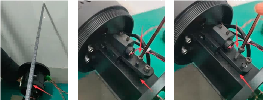
Next, extend the optical path to 0.8m — this is your target length. Watch the real-time display; the dust signal should read 0. On the Query menu, the Lv value should also be zero. Slowly turn the adjustment screw counter-clockwise to lower the laser mount. You will see the Lv rise to a peak then drop back toward zero. Stop when values hover around zero and tighten the fixation screw to lock the optics.
- Calibration Block Alignment
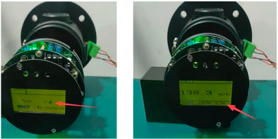
Now insert the calibration block into the path. Check the Lv reading again. If it is far from the target 2000 (e.g., ~3100), gently turn the block’s rear screw counter-clockwise to lower the reading. If the Lv reading is too small (e.g., ~270), turn clockwise to raise it. Repeat until the Lv stabilizes near 2000, indicating proper alignment.
- Final Settings and Completion
Finally, open the main menu, select “Set”, and enter the password 7844. Choose “Device”, then “Path”, and set the length to 0.8m. Return to the real-time display to confirm the optical path now shows 0.8m. The adjustment is complete!
For a visual walkthrough, check out our YouTube instructional video. If you need further help, feel free to contact us!