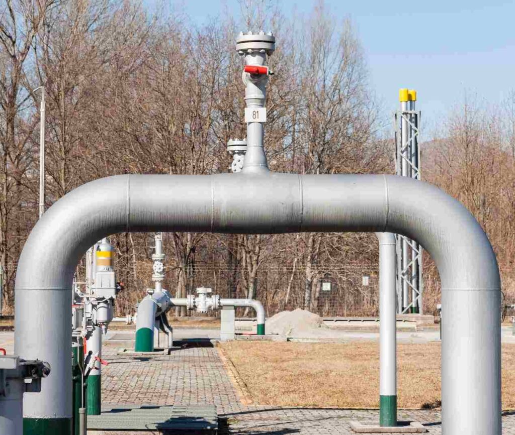
Natural gas transmission lives and dies on custody-transfer accuracy: tiny meter errors ripple into daily imbalances, disputed settlements, and inflated OPEX. The pain compounds in high-velocity, large-diameter lines where moving parts wear, pressure loss wastes energy, and field maintenance steals uptime. ESEGAS applies transit-time ultrasonics to solve this: no obstruction, negligible pressure drop, and digital diagnostics designed for stable, verifiable measurement in closed conduits—exactly the conditions of a transmission main.
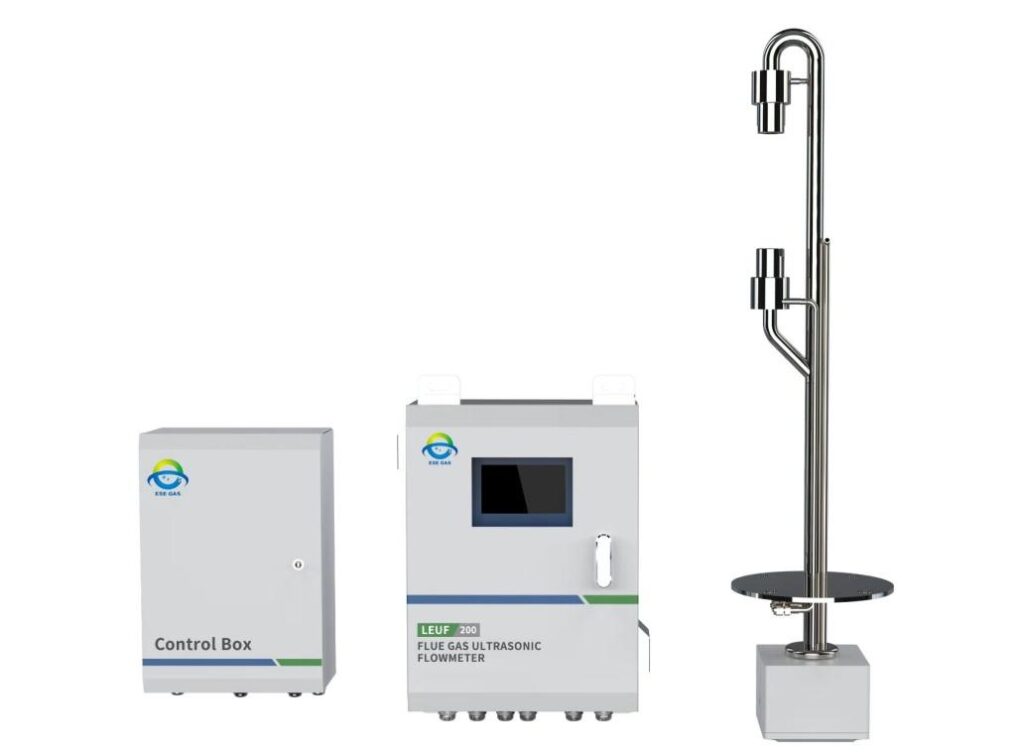
ESEGAS’s transit-time gas ultrasonic meter provides custody-grade accuracy with near-zero pressure loss, continuous diagnostics for meter verification, and integration aligned to recognized practices in natural-gas metering (e.g., ISO 17089-1 and AGA Report No. 9). It is engineered for closed-conduit applications typical of transmission pipelines, supporting temperature/pressure inputs for standard volume calculation and SCADA integration.
If you already know ultrasonics reduce pressure drop and routine maintenance, the next step is choosing and deploying them with confidence. Below, we answer the key questions transmission operators ask most—accuracy foundations, standards mapping, installation rules of thumb, diagnostics, operating envelope, TCO versus alternatives, and integration—so you can make a defensible technical and commercial decision.
Why is ultrasonic the better choice than mechanical meters in long-distance transmission?
Mechanical and differential-pressure meters add pressure loss and moving parts to a network designed to move gas efficiently. That loss shows up as compressor fuel burn and OPEX, while wear shows up as drift and downtime. The Ultrasonic Flow Meter approach removes those friction points.
- Zero/near-zero pressure loss: Ultrasonic meters read transit times through the gas; they don’t intrude into the flow, so they avoid the permanent head loss typical of orifice or turbine meters. In high-throughput lines, the energy savings are material.
- High turn-down and large diameters: Multichannel ultrasonic designs maintain accuracy across wide Reynolds ranges and large pipe sizes common in transmission
- Lower routine maintenance: No moving parts reduces wear; diagnostic data supports condition-based service rather than time-based teardown.
- Fit for modern stations: Ultrasonic meters align with contemporary standards (ISO 17089-1/AGA 9), making them acceptable for custody transfer where mechanical meters traditionally dominated.
How do transit-time and multi-path measurement improve accuracy?
Distorted velocity profiles and swirl are the enemies of accuracy. Single-path meters see a narrow slice and can be biased. A multipath Ultrasonic Flow Meter samples the profile strategically to cancel asymmetry and turbulence effects.
- Transit-time principle: The meter measures the difference in upstream vs. downstream sonic travel times. That time delta is proportional to path-averaged velocity. Summing multiple path velocities reconstructs the cross-sectional average.
- Multi-path robustness: By placing several chords across the bore, multi-path meters weight different regions of the profile, improving accuracy under swirl, elbows-out-of-plane, or partial asymmetry—conditions common in compact stations.
- ESEGAS context: ESEGAS positions its ultrasonic solution for closed-conduit gas flow and supports temperature/pressure inputs used in standard volume outputs—critical to transmission reporting.
What do ISO 17089-1 and AGA 9 require—and why does that matter for custody transfer?
Without standards, every measurement becomes negotiable. That’s costly at the settlement table. Standards make performance, installation, and verification auditable.
ISO 17089-1:2019 scope: Defines construction, performance classes for custody transfer/allocation, calibration/verification diagnostics, data outputs, and installation conditions for gas ultrasonic meters.
- AGA Report No. 9: A performance-based specification for multipath gas ultrasonics; it extends guidance on meter design, diagnostics, and installation practices for custody service. Operators and vendors widely reference it in North America.
- Implication: Selecting an ultrasonic meter designed to meet these frameworks streamlines acceptance for custody transfer and simplifies audits and dispute resolution.
Quick reference (selected themes from ISO 17089-1 / AGA 9)
| Theme | What it addresses | Why it matters |
| Performance classes | Accuracy bands and stability expectations | Sets contractual tolerance |
| Diagnostics | Meter verification, signal quality, path health | Enables on-line proving checks |
| Installation | Straight lengths, flow conditioners, disturbance effects | Reduces profile-induced bias |
What installation practices help you get repeatable, custody-grade results?
Great meters can be let down by poor piping. Inadequate straight runs, reducers, or elbows too close to the body degrade the acoustic picture—producing avoidable uncertainty. A disciplined plan protects your Ultrasonic Flow Meter’s accuracy.
- Treat upstream disturbances: Follow AGA 9/ISO guidance for straight-run allowances; add a flow conditioner if you must place elbows, tees, or valves close to the meter.
- Keep bore and alignment true: Use same-diameter spools, concentric reducers (if needed), and precise meter centering to preserve chord geometry.
- Instrument placement: Place temperature/pressure taps per good practice to avoid local bias and to support standard-volume computation in the flow computer or meter.
What diagnostics should operations watch—and what actions do they trigger?
In unmanned stations, the first sign of trouble should be a diagnostic—not a monthly volume imbalance. Rich self-monitoring lets your Ultrasonic Flow Meter call for attention before accuracy drifts.
- Signal quality & SNR by path: Declining SNR or intermittent time-of-flight correlation suggests fouling, wet gas slugs, or transducer issues → inspect strainers/filters, check condensate management, verify transducer health.
- Path-to-path velocity symmetry: Shifts in chord ratios flag profile distortions (e.g., valve position changes, upstream work) → review station line-up and recent maintenance.
- Embedded meter verification: Standards encourage using diagnostics to support in-situ verification between calibrations—reducing unnecessary removals.
Example diagnostic quick-map
| Diagnostic | Indicates | Typical response |
| Low SNR on one path | Localized fouling or wetting | Inspect bore, drains, transducer |
| Consistent chord asymmetry | Profile distortion | Check upstream fittings/valves |
| Drift in speed of sound vs. gas model | Composition change or temp error | Validate gas properties & sensors |
How do pressure, temperature, pipe size, and gas quality affect performance?
Transmission isn’t a lab. Pressure swings, temperature gradients, moisture, and particulates can all nibble at accuracy. The Ultrasonic Flow Meter design and your station layout should anticipate them.
- Best-case medium: Dry, high-pressure natural gas provides clean acoustic paths and strong signal margins. Persistent liquids/aerosols attenuate signals; manage with separators/drip pots and sensible meter siting.
- Temperature/pressure inputs: Pair the meter with T/P to compute standard volume (SCF/Sm³) in compliance with reporting needs. ESEGAS highlights optional T/P integration on its product line.
- Large diameters: Multi-path architectures scale well to big bores; ensure straight-run or flow conditioning per standards to keep profile bias in check.
What’s the TCO case versus turbine, orifice, or Coriolis?
Purchase price is obvious; pressure loss and maintenance are the hidden giants. In long-life transmission service, the Ultrasonic Flow Meter typically wins on avoided head loss and fewer interventions.
- Energy cost of head loss: Orifice and some mechanical technologies impose permanent pressure drop that compressors must overcome; ultrasonics do not, saving fuel and emissions.
- Maintenance intervals: No moving parts means fewer inspections and rebuilds; diagnostics target work where it’s actually needed.
- Custody-transfer acceptance: Compliance with ISO/AGA frameworks eases commercial acceptance, reducing soft costs (audits, disputes).
Illustrative comparison (conceptual)
| Attribute | Ultrasonic | Turbine | Orifice | Coriolis (big line) |
| Pressure loss | ~None | Moderate | High | Moderate–High |
| Moving parts | No | Yes | No (but with plate wear/edges) | No |
| Typical sizes | Small → very large | Small → medium | Small → very large | Small → medium (costly when large) |
| Diagnostics | Rich, path-based | Limited | Limited | Moderate |
| Custody standards | ISO 17089-1, AGA 9 | AGA 7 | AGA 3 | API/others |
How does it fit into an existing metering station and SCADA/data governance?
Data silos make audits painful. The Ultrasonic Flow Meter’s digital outputs and event logs should flow into your historian with time sync and change control intact.
- Interfaces & computation: Use the meter or a certified flow computer to handle T/P correction, speed-of-sound checks, and standard-volume totals; forward primary variables and diagnostics to SCADA.
- Time alignment & auditability: Maintain synchronized timestamps and retain meter verification records; both ISO 17089-1 and AGA 9 emphasize verifiability for on-going accuracy assurance.
Conclusion
For transmission pipelines, accuracy, uptime, and energy efficiency are inseparable. By removing pressure loss, eliminating wear parts, and embedding rich self-verification aligned to ISO 17089-1 and AGA 9, ESEGAS’s Ultrasonic Flow Meter provides a defensible, low-OPEX path to custody-grade measurement. Pair disciplined installation with diagnostics-driven maintenance, and you’ll protect both the commercial balance and the operational heartbeat of your gas network.