

What is the ESEGAS LEUF-200 Ultrasonic Flow Meters System?
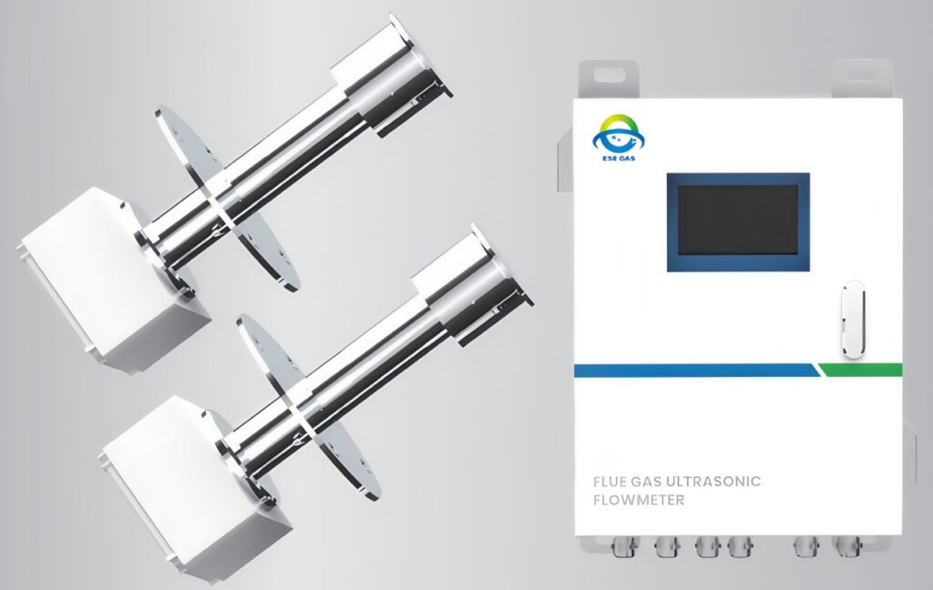
The ESEGAS LEUF-200 Ultrasonic Flow Meters system comprises the following key components:
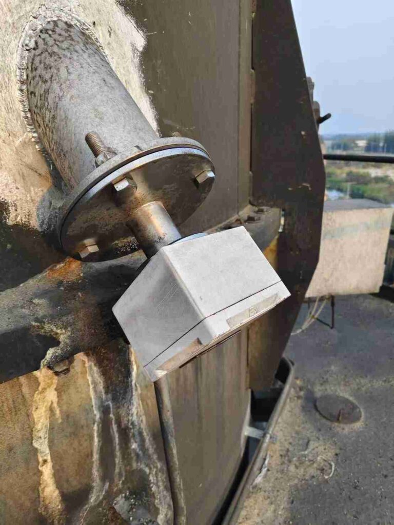
- LEUF-200 Transceiver: A combined transmitter/receiver unit responsible for the emission and detection of ultrasonic pulses.
- Flanged Spool Piece (Material Optional): A flanged section of pipe, with material options available to ensure compatibility. It facilitates secure mounting of the transceiver to the flue.
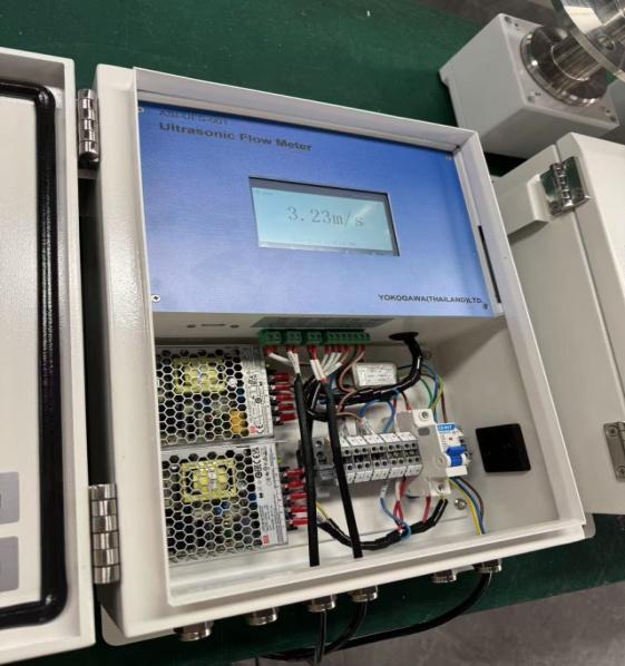
- LEUF-200 Evaluation Unit: This unit provides signal processing, system control, and signal input/output functionalities. It analyzes the received signals to determine flow characteristics.
- Interconnecting Cable: This cable provides analog or digital signal communication between the transceiver and the evaluation unit, ensuring reliable data transmission.
What is the Working Principle of the ESEGAS LEUF-200 Ultrasonic Flow Meters?
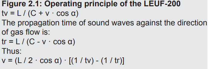
The LEUF-200 measures gas flow rate using ultrasonic pulse transit time. Ultrasonic transducers are installed on the flue sides at an angle to the gas flow (see Figure 2.1). This angle, α, and the gas flow rate, v, determine the transit time with and against the flow. A greater transit time difference indicates a faster gas flow. Temperature and pressure variations do not affect the flow rate calculation.
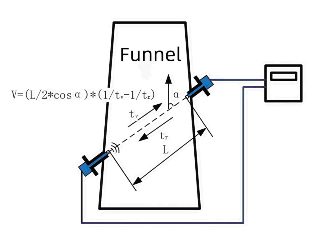
(see Figure 2.1: Operating principle of the LEUF-200)
Given the measurement path L, sound velocity c, and installation angle α, propagation time is calculated. The measurement path L equals the actual distance the sound wave travels in the gas. Gas velocity (v), measurement distance (L), installation angle (α), downstream transmission time (tv), and upstream transmission time (tr) are key parameters.
What Conditions Determine the Volume Flow?
The gas flow rate depends on the measurement distance and installation angle. These parameters are used because the transmission time is measured independently4. Volume flow is calculated using the flue’s geometric dimensions. Standard conditions require temperature, pressure, and humidity for accurate flow rate calculation.
What is the Application of the ESEGAS LEUF-200 Ultrasonic Flow Meters in Gas Detection?
The LEUF-200 Ultrasonic Gas Flow Meters accurately measure the flow rate and volumetric flow of gases within ducts, flues, and stack emissions. Suitable for both conditioned and raw gases, it accommodates closed-pipe and open-channel flow configurations. Key applications include:
- Process Control and Optimization: Chemical plants, pharmaceutical manufacturing, grain and food processing, plastics production, and refining operations.
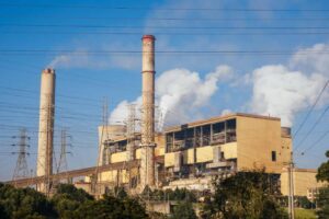
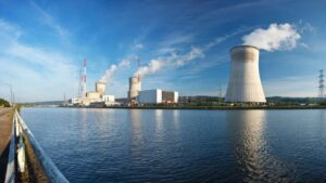
- Process Measurement and Emissions Monitoring: Utility plants, including power generation facilities and boiler exhaust monitoring.
- Waste Treatment Monitoring: Waste incineration plants for exhaust emission analysis.
- Industrial Gas Flow Measurement: Applications within the chemical, steel, and related basic industries.
- General Industrial Applications: Versatile gas flow measurement across diverse sectors.
What are the Technical Advantages of the ESE-LEUF-200 Ultrasonic Flow Meter?
The ESE-LEUF-200 Ultrasonic Flow Meter offers distinct technical advantages. Installation is straightforward; featuring paired ultrasonic sensors and a controller. Multiple interfaces facilitate diverse signal I/O, suiting various applications. It measures across the entire flue diameter. Gas flow rate measurements correlate with temperature, pressure, and composition. Real-time signal correction ensures strong interference immunity. A high-precision integrated circuit ensures accurate measurements. Automatic self-testing is performed via a routine check cycle.
How Many Flow Rate Measurement Technologies in CEMS Applications?
To ensure effective emissions monitoring, Continuous Emissions Monitoring Systems (CEMS) rely heavily on precise flow rate data. This data is typically gathered using a range of technologies, including robust S-Type Pitot Tube systems, thermal mass flow meters for direct measurement, ultrasonic flow meters, differential pressure (DP) transmitters, and opacity units. (https://escspectrum.com/home/learn-and-support/source-blog/understanding-continuous-emissions-monitoring-systems-cems-a-comprehensive-guide/)
To give users a clear picture of the pros and cons of different methods—and to help them pick the best measurement approach for their needs—ESEGAS has put together a comparison chart of various flow rate measurement technologies.
Flow Measurement Methods Comparison
| Features | S-Type Pitot Tube systems | Thermal mass flow meters | Ultrasonic flow meters | Differential pressure (DP) transmitters | Opacity units |
| Working Principle | Measures flow velocity at a single point using the difference between static and dynamic pressure | Measures the heat transfer rate to determine mass flow. Heat required to maintain constant temp of flowing fluid is proportional to its mass flow rate | Measures the velocity of a fluid using ultrasonic waves. | Measures the pressure difference between two points in a system, often across a restriction | Measures the amount of light that is blocked by particles in a gas stream |
| Advantages | 1) Low cost. 2) Simple. 3) Minimal pressure loss. 4) Can be inserted into pressurized pipelines. | 1) Wide range of applications. 2) Cost-effective. 3) Easy installation. 4) Low maintenance. | 1) Measures wide range of gas flow rates. 2) Low maintenance (no moving parts). 3) Non-intrusive. | 1) High accuracy and precision. 2) Versatile. 3) Durable. 4) Compatibility with standard protocols. 5) Real-time monitoring and diagnostics. | 1) Direct measurement of particulate concentration. 2) Relatively simple to operate. |
| Disadvantages | 1) Errors from velocity profile changes. 2) Plugging of pressure ports. 3) Measures only at one point. | 1) Fluid limitations (not for corrosive fluids or fluids with low thermal conductivity). 2) Accuracy limitations. 3) Calibration requirements. | 1) Installation requirements. 2) Higher initial cost. 3) Sensitive to flow profile disturbances. 4) Temperature and pressure limitations. | 1) Installation and maintenance. 2) Sensitivity to vibration 3) Initial cost. 4) Complex calibration. 5) Limited for low differential pressures. | 1) Indirect measurement of flow. 2) Affected by particle size and composition. 3) Requires careful calibration and maintenance. |
| Suitable Scenarios | 1) Secondary flow measurements where cost is a major concern. 2) Large pipe or duct diameters. | 1) Oil and gas, chemical, pharmaceutical, food processing. 2) Measurement of liquids, gases and steam. | 1) Gas flow measurement in various industrial applications. | 1) Flow measurement. 2) Level measurement. 3) Monitoring pressure across filters. 4) Valve monitoring. 5) Density and specific gravity measurement. 6) Safety systems. | 1) Monitoring particulate emissions from boilers and industrial processes. |
| Cost | Low | Cost-effective | High | High | Medium to high |
| Maintenance | Low maintenance | 1) Low maintenance. 2) Periodic calibration may be required. | Low maintenance | Requires skilled technicians for calibration | Requires regular cleaning and calibration. |
What are the Future Development Trends?
Future ultrasonic flow meters will be more intelligent and automated. They will adapt to different gases and conditions. Self-calibration and self-diagnosis will be included. They will integrate with the Industrial Internet and IoT. Multifunctional integration is another trend. Future flow meters may monitor gas temperature, pressure, and humidity. Miniaturization and portability will expand applications. They will be used in mobile monitoring and on-site detection. They will also be more environmentally friendly. The production and use will be more energy-saving1. Material selection will focus on recyclability.