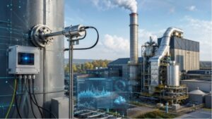


In industrial operations, a process gas analyzer often forms the nerve center of gas monitoring. Getting its readings wrong can lead to serious consequences — regulatory fines, safety hazards, or costly process inefficiencies. Yet validating and calibrating such analyzers is far from trivial, especially when the environment is unforgiving.
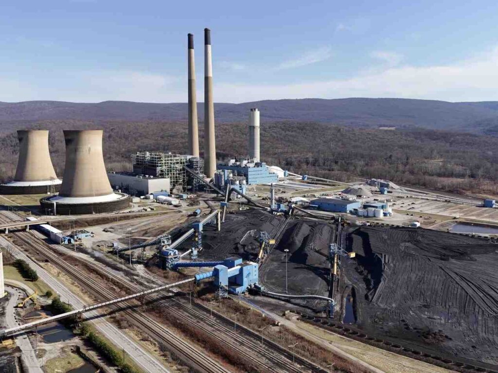
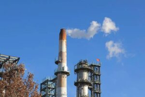
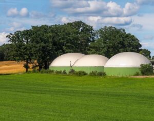
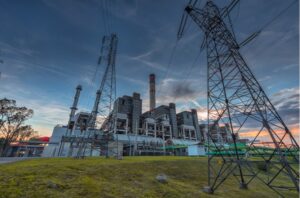
(Coal and New gas power plants )
Harsh site conditions—high temperature swings, corrosive gases, heavy particulate loads, vibration, and contamination—constantly push sensors toward drift, misalignment, or failure. Over time, small errors accumulate, jeopardizing data integrity. Without rigorous validation and calibration, you lose confidence in measurements—and potentially in the safety and compliance of your entire plant.
What Key Fundamentals Define a Process Gas Analyzer?
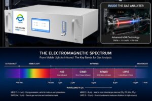
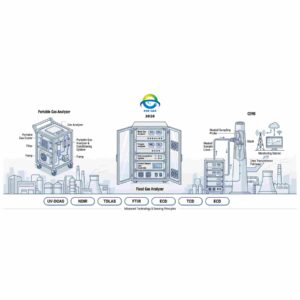
A process gas analyzer refers to instrumentation that continuously measures the composition of a gas stream in an industrial process. Such analyzers often operate under demanding conditions and must deliver real-time, reliable data. Many modern systems (for example from ESEGAS) combine multiple sensing principles to cover complex gas mixtures.
Common analyzer types include:
- Gas Chromatograph (GC): Separates gas species over time via carrier gas and column, and then detects each species in turn.
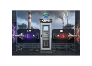
- Non-Dispersive Infrared (NDIR): Uses infrared absorption bands to quantify gases like CO₂, CH₄, or CO.
- Paramagnetic (for O₂): Exploits oxygen’s magnetic susceptibility compared to other gases.
- Electrochemical Sensor: Uses redox reaction at electrodes; common in detecting toxic or trace gases.
- Tunable Diode Laser Absorption (TDLAS / laser spectroscopy): Probes specific absorption lines with high selectivity and speed (e.g. OA-ICOS)
Each technique has trade-offs in range, speed, stability, and sensitivity. A well-engineered analyzer often layers sensors or allows cross-compensation among channels.
Typical measurement characteristics:
- Measurement ranges may span from ppb (parts per billion) to percent levels, depending on gas and sensor choice.
- Sensitivities (minimum detectable change) often lie in low ppm or even sub-ppm regions.
- Dynamic behavior: response time (T₉₀), stability under perturbations, and drift over hours or days vary by sensor type.
Understanding these fundamentals helps you choose and operate analyzers with awareness of their limits and vulnerabilities.
Validation and Calibration are often used interchangeably—but in gas measurement practice, they have distinct roles:
- Calibration: The act of adjusting an analyzer’s output to match known reference standards. You feed certified calibration gas and align zero, span, slope, or scale factor.
- Validation: The broader process of verifying that the full measurement chain—including the sampling system, lines, filters, and sensor—meets defined performance criteria for bias, precision, linearity, and stability under actual operating conditions.
In harsh environments, calibration alone can mislead you, because the sampling path (exposure to heat, fouling, contamination) may introduce unmeasured errors. Validation ensures that your measured value truly reflects the real gas conditions, not just the sensor’s ideal response after calibration.
Thus, calibration is a step within validation—but validation demands testing under real conditions, not just in “clean” calibration mode.
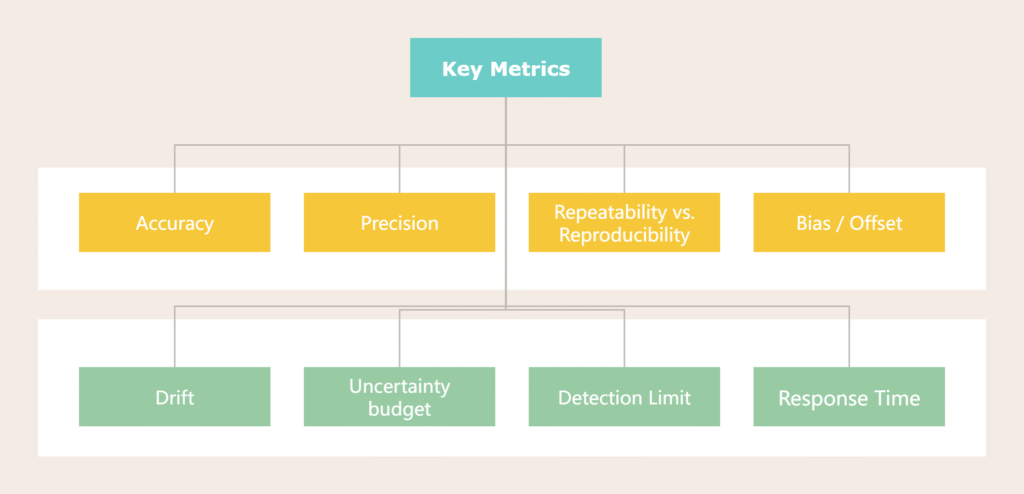
Key Metrics and Concepts
To validate or calibrate meaningfully, you must grasp the key performance metrics that describe measurement quality:
- Accuracy: How close the measured value is to the true (reference) value.
- Precision: The spread (scatter) when repeating measurements under identical conditions.
- Repeatability vs. Reproducibility: Repeatability is variation under same conditions; reproducibility includes variation across different days, operators, or instruments.
- Bias / Offset: A persistent systematic shift from the true value.
- Drift: Gradual change of the sensor response over time (zero drift, span drift).
- Zero drift / span drift: Shift at low end (zero) or high end (span) of the scale.
- Uncertainty budget & Traceability: You must account for every source of error (sensor, gas standard, temperature, pressure). Calibration gases must come with certificates traceable to recognized labs (ISO 17025).
- Detection Limit: The smallest concentration change you can reliably discern above noise.
- Linear Range: The concentration range where the sensor responds proportionally to gas concentration.
- Cross-interference: Influence of one gas species on another’s reading, especially in complex mixtures.
- Response Time (e.g. T₉₀): Time to reach 90% of final reading after step change.
Together, these metrics let you define acceptable performance thresholds (e.g. ±2 % of reading, drift < 1 % over 24 h) and decide whether your analyzer is still valid.
What Challenges Do Harsh Conditions Impose on a Process Gas Analyzer?
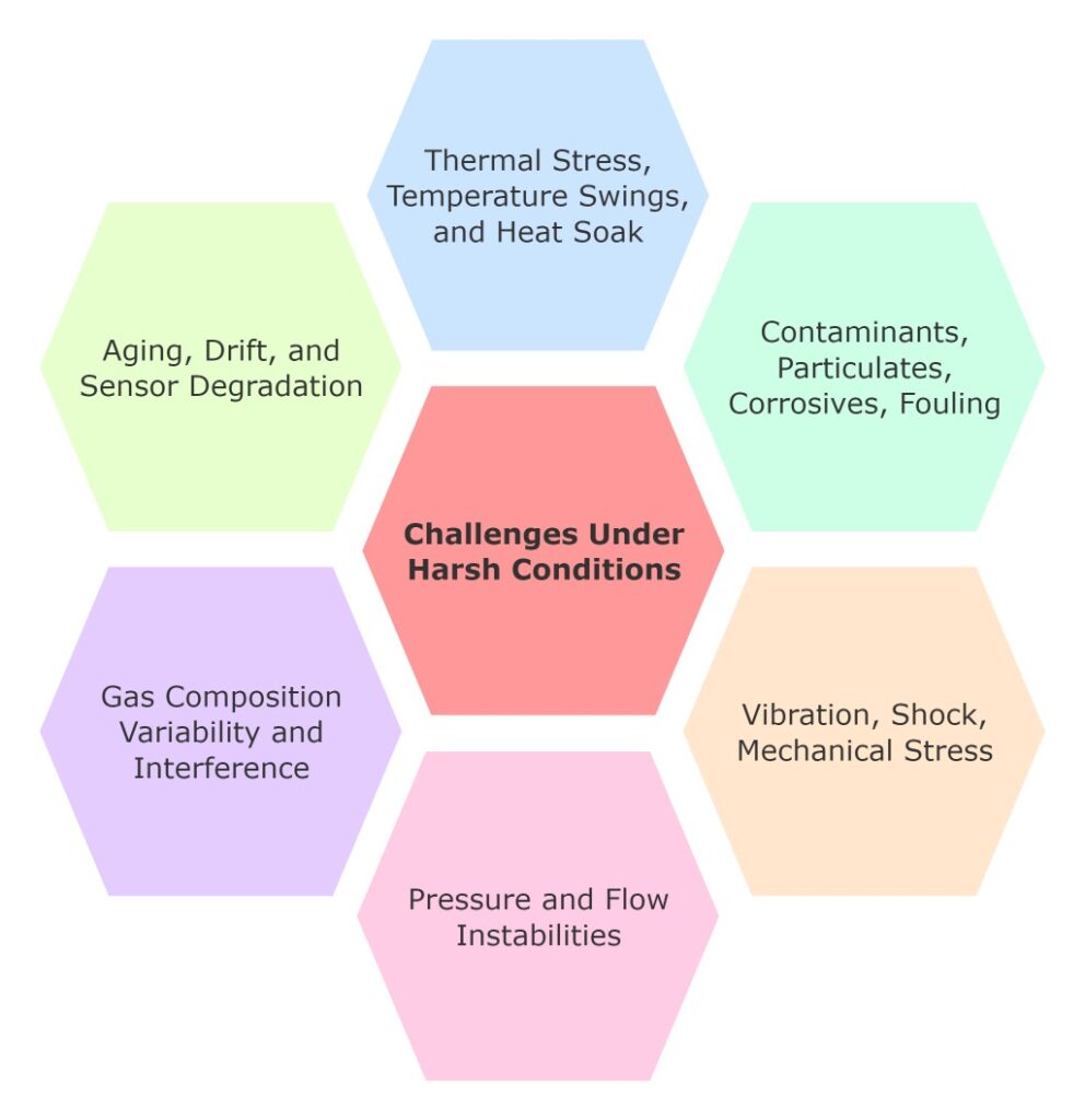
1. Thermal Stress, Temperature Swings, and Heat Soak
High ambient temperatures or rapid temperature swings can stress both electronics and sensor elements. The gas’s density changes with temperature, which may skew concentration readings if pressure compensation lags. Moreover, the sample line and calibration line may warm or cool at different rates—this thermal lag leads to mismatch between calibration and actual measurement paths. Over time, such differences introduce bias. Effective management of thermal gradients is critical, especially in hot stacks or furnace exhaust environments.
2. Contaminants, Particulates, Corrosives, Fouling
Dust, soot, acid gases, or chemical vapors often coexist in industrial exhaust streams. These can adsorb onto sensor surfaces, coat optical windows, or poison catalysts. For example, sulfur compounds may impair catalytic sensors; particulates may block flow or degrade filter efficacy. To mitigate this, one must use upstream protective measures: filters, scrubbers, inert coatings, heated sample lines, and back-purge systems. Each layer of protection reduces the burden on the analyzer and helps maintain calibration fidelity.
3. Vibration, Shock, Mechanical Stress
In plants with heavy machinery, analyzers may face vibration and shock. This motion can disturb flow stability, misalign optical paths, and affect pressure regulation valves. Even micro-vibrations may undermine delicate optical alignments or mechanical seals. As a result, the measurement path may drift, or flow disturbances may cause erroneous transients. Engineers must mount analyzers on vibration-absorbing supports or isolate critical components to preserve stability.
4. Pressure and Flow Instabilities
Process streams often fluctuate in pressure or flow. Sudden transients or pulsations propagate into the sampling train. These dynamics may change sample velocity, cause pressure drops, or introduce turbulence. The sampling lines themselves may experience changes in Reynolds number or partial flow separation. All of these affect how representative the gas sample is. Without compensating for these instabilities, analyzer readings drift unpredictably.
5. Gas Composition Variability and Interference
In a stable lab, you know exactly which species to measure. In real industrial gas, unexpected species or background fluctuations can hit you with cross-sensitivity errors. A sensor tuned for CO may respond weakly to hydrocarbons, or water vapor might quench fluorescence readings. In complex mixtures, you must design for interference correction, or include scrubbers or measurement of interfering species so you can mathematically compensate. Otherwise, your “corrected” value might be wrong.
6. Aging, Drift, and Sensor Degradation
Even in benign conditions, sensors slowly drift over time. In harsh environments, the pace accelerates. Components degrade: optical coatings darken, membranes permeate, catalysts lose activity, electronics shift baseline. Baseline shifts accumulate, and drift erodes confidence in your readings. Without periodic revalidation or recalibration, your data becomes unreliable.
To truly trust your analyzer, you must adopt more rigorous strategies: incorporate the sampling path in validation, use protective design, monitor drift continuously, and plan structured revalidation. These next sections will lay out a layered, robust approach to ensure enduring performance in even the harshest settings.
What Strategy Ensures Reliable Validation & Calibration of a Process Gas Analyzer in Harsh Conditions?
1. Top-Level Assurance Strategy
To ensure measurement integrity under stress, adopt a hierarchical assurance framework:
- Design for robustness
- Initial validation
- Baseline calibration
- On-line monitoring
- Periodic full revalidation
Use risk-based frequency schedules—more frequent checks where failure risk is high. Also embed feedback loops: compare analyzer readings with independent process samples or reference checks. If divergence trends emerge, trigger deeper review or revalidation.
2. Design and Pre-validation Preparations
Before you ever validate, build resilience into the system:
- Choose a rugged analyzer: hermetic seals, purge systems, hardened optics.
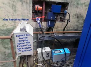
- Engineer sampling path: locate probe wisely, use heated/coated lines, install filtration and back-purge, balance flows across parallel lines.
- Place validation injection points so that calibration gas traverses the same sample path (not just the sensor).
- Add environmental sensors—measure temperature, humidity, pressure alongside the gas analyzer—to support compensation and diagnostics.
These steps reduce unmeasured errors during operation.
3. Initial Validation (Factory / Site Commissioning)
At startup, you must prove your system’s baseline:
- Perform zero drift, span drift, linearity, and response time tests in clean, controlled gas.
- Use certified calibration gases traceable to reliable labs.
- Run replicate measurement points, chart control trends, detect outliers statistically.
- Define warning and control limits; set alarms when performance degrades.
This initial validation becomes your reference “gold standard.”
4. On-Site Calibration / Adjustment under Harsh Operation
Once live, calibration becomes ongoing:
- Conduct zero-span checks at regular intervals; choose frequency based on risk and drift behavior.
- Prefer in situ injection through the sample path so calibration sees the same disturbances, rather than external bypass techniques.
- Always purge/flush before and after calibration; allow stabilization time.
- Correct for environmental parameters (temperature, pressure) in real time.
- After calibration, validate: ensure that readings now fall within acceptable error envelopes.
Calibration without post-check is not complete assurance.
5. Drift Monitoring and Trending
Even with calibration, drift creeps in. Guard against it:
- Use built-in diagnostics or compare against a secondary reference.
- Implement control charts (SPC) to spot gradual shifts before they exceed limits.
- Define drift thresholds that trigger alerts or even automatic recalibration.
- Let the system auto-flag anomalies rather than waiting for manual review.
Trend data often reveal deeper underlying problems before they show as big errors.
6. Periodic Revalidation
Full revalidation must occur periodically or after major events:
- Repeat the full suite: linearity, precision, interference tests.
- Reassess calibration offsets, sensor aging, and drift history.
- Compare to original validation baseline—note any degradation.
- If performance degrades too much, redesign or replace sampling elements or sensors.
This resets your system’s confidence level.
7. Handling Failures, Anomalies, and Corrective Actions
When things go off-nominal, you must act methodically:
- Diagnose mismatch: drift, nonlinearity, interference, or sample path issues.
- Use root cause thinking: is the fault in the sampling line, contamination ingress, optical window fouling, or hardware degradation?
- Fix via cleaning windows, replacing filters or components, or adjusting path flow.
- After repair, requalify the system—run validation tests to ensure performance is restored.
Consistency in these corrective routines builds trust that your analyzer stays reliable even in harsh environments.
Conclusion
In closing, validating and calibrating a process gas analyzer in a harsh environment is anything but trivial. Extreme temperatures, corrosive gases, vibration, flow instabilities, interference, and sensor aging all conspire to undermine measurement integrity. Yet achieving reliable, defensible gas data is essential—for process control, safety, regulatory compliance, and economic efficiency.
Don’t wait for failures. Invest proactively in robustness—better sampling design, calibration injection points, environmental compensation, and automated validation tools. Treat measurement assurance as a continuous discipline, not a one-off task. A small upfront effort in design and early validation pays dividends in long-term trust, cost savings, and fewer surprises.
If you want to discuss more solutions about process gas analyzer, contact with us please!
Frequently Asked Questions (FAQ)
Q1: What’s the difference between calibration and validation for a process gas analyzer?
A1: Calibration means adjusting the process gas analyzer’s output using known reference gases (zero, span, slope) so the readings match certified values. Validation is broader — it confirms the entire measurement chain (including sample lines, filters, temperature effects) meets pre-defined criteria (bias, precision, linearity, stability) under real operating conditions. Calibration is part of validation, but validation ensures that your analyzer works properly under actual harsh conditions.
Q2: How often should you calibrate a process gas analyzer in a harsh industrial environment?
A2: The ideal calibration frequency for a process gas analyzer depends on risk, drift behavior, and environmental stress. In harsh settings, daily or weekly zero/span checks may be required, with full calibration or validation at longer intervals (e.g. monthly, quarterly, or annually). Use a risk-based approach: if drift or failures are costly, increase frequency. Also, monitor trends to adapt your schedule dynamically.
Q3: How do thermal gradients and temperature swings affect analyzer calibration?
A3: Thermal gradients cause different parts of the system—sample line, calibration line, sensor—to heat or cool at different rates. That thermal lag produces bias because calibration gas and process gas experience different temperature profiles. Also, gas density and pressure compensation shift with temperature, skewing concentration readings. Reliable process gas analyzer calibration must account for and mitigate these temperature effects.
Q4: Can contamination, fouling, or particulates invalidate calibration over time?
A4: Yes. Contaminants may adsorb on sensor surfaces or coat optical windows. Particles might block paths or damage filters. Chemical fouling can poison catalysts or alter sensor sensitivities. Over time, these degrade performance such that a prior calibration no longer holds. That’s why validation must include “real gas” challenges and protective sampling design (filters, scrubbers, purge lines).
Q5: Should calibration gas be injected upstream (through sample path) or bypassed around the sampling system?
A5: It’s best to inject calibration gas through the same sampling path (i.e. upstream injection) so it encounters the same filters, heated lines, flow dynamics. That way the calibration truly reflects what the analyzer “sees.” Bypassing the sample path risks ignoring errors introduced by that path and gives a false sense of accuracy. This approach is also a key tenet in EPA/CEMS practice.
Q6: What metrics should I monitor to know if an analyzer’s calibration is degrading?
A6: Watch for:
- Drift (zero drift, span drift)
- Bias / offset shifts
- Increased scatter (precision worsening)
- Linearity deviations
- Sudden jumps or anomalies
Use control charts / statistical process control to detect trends before tolerances breach. Also compare to a secondary reference or duplicate system for sanity checks.
Q7: When should a full revalidation (not just calibration) be carried out?
A7: Full revalidation is warranted:
- After major maintenance or component replacement
- After observing repeated drift or anomalies
- On a fixed calendar schedule (e.g. annually)
- When environmental or process conditions change significantly
Revalidation should replicate the full suite of validation tests (linearity, interference testing, precision) and compare results to the original baseline.