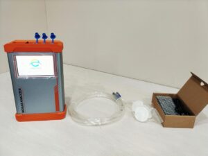
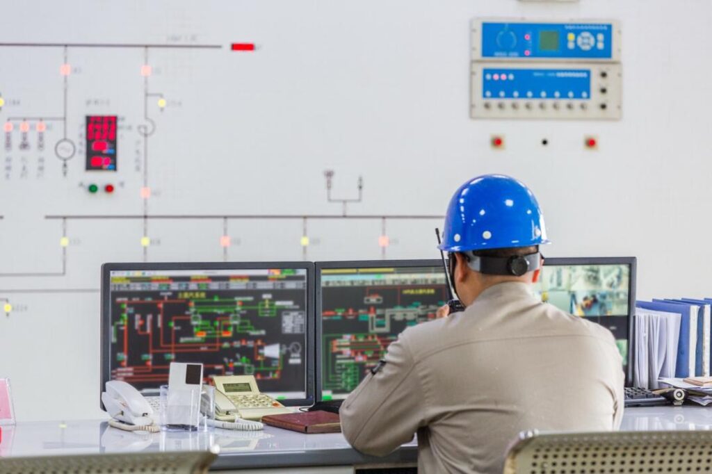
Picture this: your infrared gas analyzer runs smoothly, measuring CO or CO₂ in the exhaust stream. The display shows accurate readings — yet the control room dashboard stays flatlined. No data appears in the DCS, alarms remain silent, and process adjustments never trigger. The analyzer is working, but the system isn’t listening. It’s a silent failure that can lead to wasted fuel, compliance risks, or even unsafe operating conditions.
Integration issues like this are surprisingly common in modern plants. The problem often hides not in the analyzer’s optics or electronics, but in the layers between — wiring mismatches, scaling errors, or communication settings that prevent the analyzer from “talking” to the control system. The good news? These failures are rarely fatal. With proper planning and coordination between instrumentation and automation teams, they can be diagnosed and prevented.
This article unpacks why an infrared gas analyzer might fail to communicate with your PLC or DCS — and how to fix it. We’ll move from basic integration concepts to deeper technical and organizational causes, covering everything from signal interfaces and protocols to system architecture and commissioning.
What Does “Integration” Mean for an Infrared Gas Analyzer?

In industrial facilities, integration refers to how an infrared gas analyzer shares its data and status with the control infrastructure. It means more than just measuring gas concentrations—it means transmitting concentration, diagnostic, and alarm data into systems like PLCs, DCS, or SCADA. This connection is vital so that control logic, alarms, historical trends, and automated adjustments can all act on the analyzer output.
Common Integration Interfaces
To talk with a control system, analyzers use one or more standard interfaces:
- Analog outputs: Examples include 4–20 mA or 0–10 V signals that represent concentration or status.
- Digital protocols: Common ones in industry are Modbus (RTU/ASCII), OPC (classic or OPC UA), HART, and EtherNet/IP.
- Discrete signals / relays: Fault, alarm, and status relay contacts or digital I/O lines.
- Hybrid / gateways: A converter or gateway may bridge between analog and digital domains, or between incompatible protocols.
When an infrared gas analyzer supports both analog and digital outputs, it offers flexibility to integrate into various control architectures.
Why Does Integration Matter?
Integration is the bridge that turns raw gas sensor readings into actionable control and decision support. Its importance includes:
- Real-time control: The control system can adjust process variables (e.g. oxygen flow, fuel rate) based on gas levels.
- Alarming & interlocks: If a concentration goes out of range, control logic can respond immediately.
- Data logging & trends: Historical records in the DCS/SCADA help optimize process performance and enable diagnostics.
- Automated adjustment: Instead of manual tuning, loops can self-adjust using analyzer feedback.
- Regulatory reporting: Emissions or compliance data often must be archived or sent to external systems.
Without seamless integration, the analyzer becomes an island: valuable measurements sit unused, and the plant misses optimization and safety opportunities.
Data Generation vs. Data Ingestion: A Critical Distinction
It is tempting to think the analyzer’s job ends at “measuring and outputting.” But the real challenge lies in data ingestion: how the control system receives, understands, and uses that data.
- Data Generation is what the infrared gas analyzer itself does: measuring concentrations, generating signals, setting alarms.
- Data Ingestion is how the control system accepts those signals: scaling, interpreting units, mapping tags, validating status, and embedding data into control logic or archives.
Many integration failures stem not from measurement, but from misinterpretation—incorrect scaling, mismatched units, or missing functional mapping of diagnostics and status bits. A successful integration closes the loop between generation and ingestion.
What Are the Common Failure Modes That Prevent an Infrared Gas Analyzer from Integrating Properly?

When your infrared gas analyzer appears to work but never makes it into the DCS/PLC, the fault usually resides in the integration chain—not the optics. Below are key failure modes, grouped by layer, each with real symptoms and root insights that often hide in plain sight.
| Category | Failure Mode | Symptoms/Effects | Root Insights/WhatTo Check |
| Physical/Electrical | Loose wiring or Insufficient shielding | Sporadic signal Dropouts, noise, erratic readings | Check cable integrity, grounding, shield quality |
| Connector corrosion or contact faults | Intermittent signals,Wire breakage | Inspect connectors,Clean contacts, verify continuity | |
| Analog Interface | Range scalingmismatch | Control shows full scale or zero (“stuck” reading) | Confirm 4-20mA span mapping in both analyzer and DCS |
| Signal clipping or overdrive | Flatline at extreme values | Ensure output range does not exceed control system limits | |
| Nonlinearity or hysteresis | Output lags or deviates under load | Test linearity across range; check load conditions | |
| Digital/Protocol | Protocol mismatch or unsupported version | No data or invalid codes seen by control system | Validate protocol type (Modbus, OPC, etc.), version function codes |
| Register/address misconfiguration | Zero or default values, wrong data | Verify register maps, offsets, and addressing | |
| Baud rate, parity, or framing mismatch | Communication failures, intermittent connections | Ensure come settings match exactly | |
| Data Semantics& Units | Unit mismatch (ppm vs. percent, etc.) | Control interprets signal incorrectly | Standardize units and scaling factors across systems |
| Tag mapping/Identity mismatch | Wrong analyte,tags mislabeled,alarms inactive | Align tag naming, ensure metadata consistent | |
| Missing status or diagnostic mapping | No fault, health, or status signal in DCS | Map diagnostic bits and status outputs | |
| Timing/ LatencyIssue | Slow polling or refresh rate | Control loops lag, data feels stale | Increase update frequency, reduce delays in path |
| Buffering/ stale data | Getaway holds old data too long | Check device buffers, queue depths, commit policies | |
| Asynchronous update cycles | Analog and digital channels conflict or misalign | Synchronize update timing or use timestamp validation | |
| Organizational& Planning | Lack of integration specification | Onsite confusion, mismatches, delays in commissioning | Establish formal interface specs in design phase |
| Siloed instrument/control teams | Each team does its part in isolation | Promotecross-discipline review and integration planning | |
| Inadequate documentation or versioning | Tag mappings, firmware changes drift over time | Keep versioned maps, controlled changes, audit trail |
How Should You Architect Integration of an Infrared Gas Analyzer with Your Control System?
In modern industrial plants, integrating an infrared gas analyzer into your control strategy means more than connecting wires. It involves layering architecture, managing protocols, and ensuring data flows smoothly—and safely—up through your control and supervisory systems. Let’s walk through the critical architecture and best practices, so you can build an end-to-end, reliable link from analyzer to control.
1. Architectural Layers: Establishing the Foundation
Think of your system in four stacked layers:
- Field Layer: This is the analyzer itself—where the infrared gas analyzer measures gas composition, provides concentration data, status, and diagnostics.
- Interface Layer: Signal conditioners, gateways, or protocol converters sit here. They translate signals, normalize data, and protect the integrity of communication.
- Control Layer: This includes your PLC or DCS, which receives the data, drives control loops, sets alarms, and logs trends.
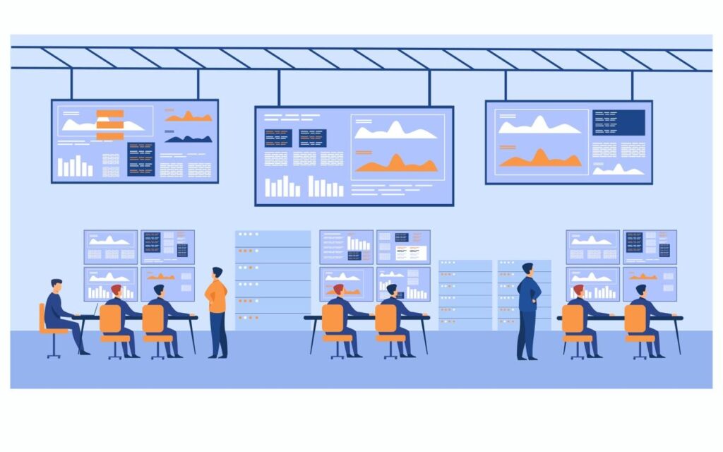
- Supervisory Layer: SCADA or historian systems aggregate data from multiple analyzers and control loops for reporting, analytics, and compliance documentation.
When you clearly define each layer, you can assign responsibilities, manage data flow, and detect where integration might fail.
2. Gateway & Protocol Bridging: Making Systems Speak Seamlessly
Often the bottleneck in integration appears when the infrared gas analyzer uses one protocol (for example Modbus RTU), while the control system expects another (such as OPC UA). At this point a gateway or protocol converter bridges the gap:
- Edge devices can convert analog to digital, Modbus to OPC, or even legacy protocols to modern IIoT endpoints.
- Good practice: maintain translation logic in the gateway rather than piling complexity into the DCS.
- Consider latency, device licensing, and version control of converters.
Since recommended standards like OPC UA support secure, standardized data models. Using such bridges ensures your analyzer data is consumable—not just shared.
3. Signal Conditioning & Normalization: Ensuring Clean, Consistent Data
Raw signal from an infrared gas analyzer may need conditioning before it enters your control system:
- Filtering removes noise or spikes caused by the sampling system or electrical interference.
- Scaling & linearization convert raw counts or voltages into meaningful units (ppm, % vol).
- Isolation protects your control system from surges or ground-loop faults.
- Multiplexing lets multiple analyzers share common hardware or bridge input constraints.
These steps ensure the control system receives reliable, properly formatted data. Overlooking them often leads to erratic control behavior.
4. Metadata & Tag Management: Aligning Semantics and Units
Accurate data is useless if mislabeled or misinterpreted. Proper tag and metadata management is essential:
- Adopt standard naming conventions, like “GA_CO_FUEL” for analyzer CO reading.
- Ensure units, engineering limits, alarm thresholds, and diagnostics are included in tag definitions.
- Maintain a tag registry where each input (concentration, status, fault code) is documented.
When multiple systems treat the same signal differently (for example ppm vs % vol), confusion or mis-control follows. Standardization reduces human error and enhances system clarity.
5. Health & Diagnostics Integration: Monitoring Instrument Condition
Your infrared gas analyzer is not just a sensor—it is a complex instrument with health status, error flags, and diagnostics. Effective integration means:
- Propagating health flags (e.g., lamp fault, window contamination) into your control system.
- Mapping error codes or warnings so that automated logic or operators can respond proactively.
- Logging diagnostics for trend analysis—so instrument condition supports predictive maintenance.
By integrating health data, you shift from “the analyzer is reading OK” to “the analyzer is healthy and trusted”—which improves operator confidence and reduces unplanned downtime.
6. Latency, Polling & Scheduling: Balancing Real-Time & Reliable
Integration isn’t just about connectivity—it’s also about timing:
- Decide update rates: rapid for control loops, slower for archival logs.
- Manage buffering: gateways or networks may queue data, causing stale values if not tuned.
- Handle failover: if a path fails, ensure alternate communication or alarm escalation is in place.
- Synchronize analog and digital updates: misalignment between channels can cause inconsistent logic responses.
When time-sensitive data from an infrared gas analyzer is delayed, control actions lag and undermine performance.
7. Security & Permissions: Protecting the Data Path
As you integrate more deeply, security becomes crucial:
- Use authentication, authorization and encryption in protocol layers (e.g., OPC UA secure mode).
- Prevent unauthorized writes to analyzer settings or DCS parameters—especially if remote access is allowed.
- Maintain clear change-control and permission models so only qualified personnel adjust tag mappings or gateway configurations.
A compromised integration link can result in false data, control mis-actions, or compliance breaches.
By implementing these practices, you transform your infrared gas analyzer from a standalone performance device into a fully integrated instrument that drives process control, safety decisions and compliance reliability.
Conclusion
Integration failures in industrial settings often don’t stem from the analyzer itself, but from the interface layers, data semantics and timing issues. In the case of an infrared gas analyzer, the unit may generate accurate measurements, yet none of those values reach your PLC/DCS reliably or in the right form. However, with a structured planning approach—defining architecture, normalizing interfaces and mapping metadata—you can bridge that gap. In short: it’s not just about measurement; it’s about meaningful transmission and consumption.
If you’ve encountered integration problems—or simply want to ensure your analyzer is fully optimized—our expert team is here to help. Visit our website to explore deeper solutions or contact us directly for a consultation tailored to your plant. Let’s make your infrared gas analyzer truly talk.
FAQs:
Q1: What prevents an infrared gas analyzer from sending data to my DCS or PLC?
A: An infrared gas analyzer may fail to send data because of mismatched signal types (e.g., analog vs. digital), wrong communication protocol settings, unit/scale mismatches, or missing wiring and grounding. In many cases the analyzer works locally but the control system never “reads” the data correctly.
Tip: Check whether your analyzer’s output (4-20 mA, 0-10 V, Modbus, OPC UA, etc.) matches the control system’s input expectations.
Q2: How do I know if my infrared gas analyzer’s communication problem is analog or digital?
A: Start by identifying whether your infrared gas analyzer transmits via analog (4-20 mA, 0-10 V) or via digital protocol (Modbus, OPC UA, HART, EtherNet/IP).
- If you see a flat or maxed-out analog reading in the DCS but valid local display, it’s likely analog mismatch.
- If you see “no data,” “invalid register,” or “communication fault” in status, it’s likely digital protocol failure.
Once you know the type, you can proceed with matching the wiring, scaling, and protocol settings.
Q3: Why does my infrared gas analyzer show correct local readings but wrong values in my SCADA system?
A: Your infrared gas analyzer may be producing valid local data, but the control/SCADA system may misinterpret it due to unit mismatches (ppm vs % vol), wrong tag mapping, or missing diagnostics/status registers. In other words, data generation is working, but data ingestion fails. To fix this:
- Verify tag names and metadata (units, range, scaling) match exactly.
- Ensure the control system interprets the value the same way the analyzer outputs it.
- Map the status/health bits so that the SCADA system can trust the analyzer’s reading.
Q4: Can latency, polling rate or gateway buffering block my infrared gas analyzer from integrating properly?
A: Yes — even the best infrared gas analyzer might “talk,” but if the data arrives too slowly or gets stuck in buffers it might as well be silent. For example:
- A gateway polling interval of 30 s may delay control logic that expects 5-s updates.
- Buffered data may present stale values to your PLC.
- Mismatched update scheduling between analog and digital channels may confuse control logic.
Therefore: check polling intervals, buffer depth, buffer flush rates, and gateway/edge device settings.
Q5: What steps should I take to ensure my infrared gas analyzer integrates smoothly with my control system?
A: To integrate your infrared gas analyzer reliably:
- Write an integration specification early — list outputs, units, protocols, diagnostics.
- Match the analyzer output type (analog vs digital) to control system input, including scaling and wiring.
- Use a protocol gateway or signal conditioning device if facing mismatches in communication standards.
- Standardize tag naming, units, engineering limits, alarms and status codes across systems.
- Test the full chain: analyzer → interface → control system → SCADA, under real load and conditions.
By following these steps you align data generation and data ingestion, making your analyzer a true part of the control ecosystem.