Thermal Conductivity Detectors (TCDs) play a starring role in gas chromatography. They track tiny shifts in a gas’s heat-transfer ability to spot different compounds. Unlike flame or electron-capture detectors, TCDs deliver universal detection without destroying samples. This quality makes them ideal for monitoring inert gases, permanent gases, and trace analytes in one run.
Moreover, TCDs offer:
- Robustness – They withstand harsher conditions without frequent breakdowns.
- Linearity – Signals grow predictably with concentration, simplifying calibration.
- Non-destructive analysis – Samples emerge intact for further testing.
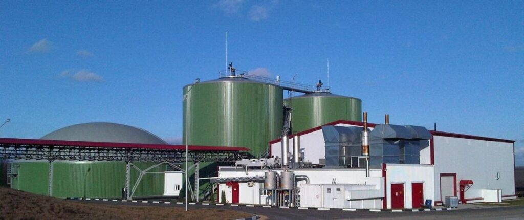
As a result, labs trust TCDs for air-quality checks, petrochemical purity tests, and biogas monitoring. In the next sections, we’ll unpack the physics behind thermal conductivity,
How Do Thermal Conductivity Detectors (TCDs) Function and Compare to Other GC Detectors?
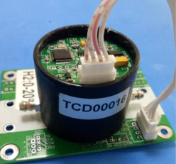
(Thermal Conductivity Detector)
Thermal conductivity underpins the operation of Thermal Conductivity Detectors (TCDs) by quantifying how readily gases transfer heat, a property that varies with molecular makeup and gas composition.
1 What Is Thermal Conductivity?
Thermal conductivity, symbolized as k, measures how efficiently a material conducts heat. In gases, this property hinges on molecular collisions that transfer energy from hotter to cooler regions. Factors like molecular weight, structure, and intermolecular forces influence a gas’s thermal conductivity. For instance, lighter gases such as helium and hydrogen exhibit higher thermal conductivities due to their rapid molecular motion and lower mass. This principle is crucial in gas chromatography, where detecting changes in thermal conductivity allows for the identification of various analytes.
Thermal conductivity detectors (TCDs) operate based on the principle that different gases conduct heat differently. The fundamental equation governing heat transfer in this context is Fourier’s Law:
Where:
- q: Heat flux (W)
- k: Thermal conductivity of the gas (W/m·K)
- A: Cross-sectional area through which heat is conducted (m²)
- dT/dx: Temperature gradient (K/m)
The sensitivity of the TCD depends on the difference in thermal conductivity between the carrier gas and the analyte. Gases like hydrogen and helium have high thermal conductivities, making them suitable carrier gases for detecting analytes with lower thermal conductivities.
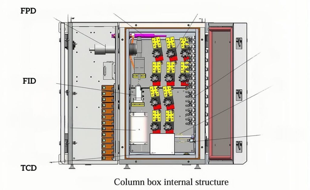
2 Detector Architecture and Signal Generation
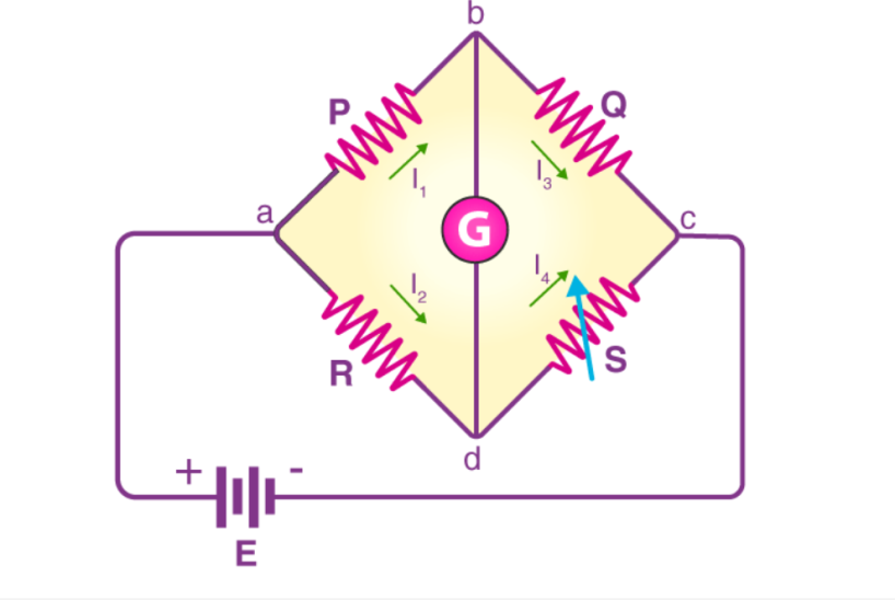
A Thermal Conductivity Detector (TCD) employs a Wheatstone bridge circuit comprising four filaments: two reference and two sample filaments. These filaments are electrically heated and situated within a temperature-controlled cell. Under baseline conditions, with only carrier gas flowing, the bridge remains balanced, and no voltage difference is observed. When an analyte elutes from the chromatographic column, it alters the thermal conductivity of the gas mixture passing over the sample filaments. This change affects the filament temperature and, consequently, their resistance, leading to an imbalance in the Wheatstone bridge. The resulting voltage difference is proportional to the concentration of the analyte, enabling its detection and quantification.
3. Comparison with Other Detection Modes
In gas chromatography, detector selection depends on the specific analytical requirements. Below is a multidimensional comparison table of five common gas-chromatography detectors: Thermal Conductivity Detector (TCD), Flame Ionization Detector (FID), Electron Capture Detector (ECD), Flame Photometric Detector (FPD), and Pulsed Discharge Helium Ionization Detector (PDHID). Primary performance metrics, operating principles, and ideal applications are summarized to help you choose the right detector for your analysis.
| Feature / Detector | TCD | FID | ECD | FPD | PDHID |
| Detection Principle | Measures change in thermal conductivity of carrier vs. analyte gas via a Wheatstone bridge of heated filaments | Ionizes organic compounds in H₂/air flame; measures resulting current between electrodes | Captures low-energy β⁻ particles on electronegative analytes; monitors drop in current | Burns analyte in H₂/air flame; uses photomultiplier tube to detect element-specific emission (e.g., S, P) | Pulsed helium plasma ionizes all compounds; measures ion‐current pulses for universal detection |
| Detection Principle | Measures change in thermal conductivity of carrier vs. analyte gas via a Wheatstone bridge of heated filaments | Ionizes organic compounds in H₂/air flame; measures resulting current between electrodes | Captures low-energy β⁻ particles on electronegative analytes; monitors drop in current | Burns analyte in H₂/air flame; uses photomultiplier tube to detect element-specific emission (e.g., S, P) | Pulsed helium plasma ionizes all compounds; measures ion‐current pulses for universal detection |
| Destructive? | No – non-destructive, sample remains intact | Yes – analyte combusts in flame | Yes – analyte interacts with β source (requires radioactive source). | Yes – analyte is burned, but partially non-destructive for specific elements | No – non-destructive, sample can be collected downstream |
| Sensitivity | Moderate: ~1 ppm (permanent gases) | High: ~1 pg C/s (parts-per-billion for many organics). | Very high for halogens: ~1 ppt (levels). | High for S/P: ~10 ppt (for sulfur) | High: ~ppt to ppb (universal), but varies with compound |
| Selectivity | Universal: responds to any gas with different thermal conductivity from carrier | Broad: responds to most hydrocarbons and organics | Highly selective: electronegative species (halogens, nitro-compounds) | Element‐specific: sulfur and phosphorus. | Universal: nearly equimolar response for all compounds |
| Linear Dynamic Range | ~10⁵–10⁶ | ~10⁷ | ~10⁴–10⁵ | ~10³–10⁶ (depending on wavelength). | ~10⁶–10⁷ |
| Typical Detection Limits | ppm–ppb for permanent gases (e.g., O₂, N₂, CO₂) | ppb–ppt for hydrocarbons | ppt for halogenated compounds | ppt for sulfur/phosphorus species. | ppt–ppb for most compounds |
| Carrier Gas Requirement | He, H₂, N₂, Ar – purity ≥ 99.999% | H₂ or He with air (fuel/oxidant) | N₂ or Ar/CH₄ with radioactive source (¹⁴C or ³H) | H₂/air | He (makeup gas) and sample gas; no flame |
| Maintenance & Safety | Low maintenance; filament aging after ~1 year | Moderate; regular flame ignition, jet cleaning | High; radioactive source handling/regulatory control | Moderate; photomultiplier tube alignment and flame management | Low-moderate; periodic plasma cleaning; no open flame |
| Ideal Applications | Permanent-gas analysis, biogas monitoring, carrier-gas purity verification | Petrochemical hydrocarbon profiling, environmental VOC screening | Environmental halogenated pollutant detection, pesticide residues | Sulfur-or phosphorus-containing compounds in petrochemical, food, and environmental samples | Trace-level universal screening in petrochemical, environmental, and forensic analyses |
Key Takeaways
- TCD serves as a robust, non-destructive universal detector for permanent gases but has moderate sensitivity.
- FID remains the workhorse for organic analysis with exceptional sensitivity and dynamic range.
- ECD excels at ultra-trace halogenated compounds but requires handling radioactive sources.
- FPD offers element-specific detection (S/P) with high selectivity.
- PDHID combines universality with very low detection limits and no flame, making it versatile for modern labs.
This table should help you weigh sensitivity, selectivity, maintenance, and application fit when selecting a GC detector.
Understanding these fundamental principles of thermal conductivity and TCD operation provides a solid foundation for effectively utilizing this detector in various gas analysis applications.
What Should You Consider When Using Thermal Conductivity Detectors (TCDs) for Gas Analysis?
How to harness TCD performance? We should examine three key factors: carrier gas choice, flow and pressure settings, and precise temperature control. Understanding the relationship among key factors and TCD’s technical parameters can help us know how we can translate theory into reliable practice.
1. Carrier Gas Selection
Choosing the right carrier gas is critical for TCD performance. Helium and hydrogen offer the highest thermal conductivities, making them ideal for maximizing signal sensitivity. However, hydrogen’s conductivity (0.1805 W·m⁻¹·K⁻¹) closely matches helium (0.1513 W·m⁻¹·K⁻¹), which can reduce response for hydrogen analysis. Therefore, argon often serves as carrier gas when detecting hydrogen to widen the conductivity gap. Nitrogen, while more stable and affordable, produces lower signal responses and may mask low-concentration analytes.
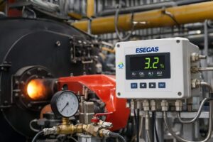
ESEGAS H2 sensor module is a good example. To get the best accuracy (±2% FS) and resolution (0.01% vol), always use ultra-high-purity gases (≥99.999%). Impurities like moisture or hydrocarbons can shift the baseline or damage the detector’s filaments. Combine this with robust gas-handling practices—like oxygen traps and inline filters—to preserve the TCD’s repeatability (≤±1% FS) and long-term performance. In short, the right gas boosts sensitivity, but the right setup preserves reliability.
2. Flow and Pressure Optimization
ESEGAS TCDs operate best within a defined flow range: 0.2–1.5 L/min. Too low, and the detector lags; too high, and the baseline becomes noisy. Balancing flow helps maintain signal integrity without sacrificing resolution. Try to tune flow near the midpoint for stable and consistent results.
Pressure fluctuations can destabilize the thermal gradient across the filaments. This leads to signal drift and increased noise. To avoid this, maintain a constant inlet pressure and use electronic pressure control if available.
Practical tip:
- Install a high-precision pressure regulator and flow dampener.
- Keep carrier-makeup gas differential below 5 psi to maintain ±2 %FS accuracy.
Linear velocity also plays a role. Faster flows reduce analysis time but may compromise separation. Slower flows enhance resolution but weaken the signal. Adjust based on your analyte’s volatility and the column’s length and ID.
3 Temperature Control
Temperature plays two key roles in TCD performance.
-First, Temperature affects the viscosity of carrier gases, which in turn alters flow behavior and heat transfer.
-Second, the detector block temperature influences the stability of the thermal conductivity measurement. Likewise, filament temperature affects peak size dramatically: a 50 °C change can halve signal amplitude.
Always match the detector temperature to the analysis conditions. Keep it above ambient, usually around 100–150°C, to prevent condensation and maintain thermal stability. Column ovens, on the other hand, affect how well compounds separate before detection. Sharp baseline and accurate detection rely on this harmony. Sudden changes in temperature—not just pressure—can flatten peaks or cause retention shifts. Stable temperature control ensures reliable response and accurate quantitation—even under varying ambient conditions (-10°C to 40°C, as per TCD specs).
With the right combination of gas, flow, and temperature, your TCD becomes a powerful, precise, and highly reliable tool for real-world gas analysis—whether you’re monitoring permanent gases, measuring biogas composition, or verifying carrier gas purity in a critical process.
What Are the Common Challenges and Maintenance Needs When Using Thermal Conductivity Detectors (TCDs)?
1. Detector Noise and Baseline Drift
Maintaining a stable baseline is crucial for accurate TCD measurements. Several factors can introduce noise and drift:
- Electronic noise: Poor grounding or electromagnetic interference can cause fluctuations.
- Gas impurities: Contaminants like moisture or oxygen can alter thermal conductivity, leading to signal instability.
- Ambient temperature changes: Fluctuations in laboratory temperature can affect detector performance.
To mitigate these issues:
- Shielding: Ensure proper grounding and minimize exposure to electromagnetic fields.
- Filtering: Use high-purity gases and install appropriate filters to remove contaminants.
- Flow dampeners: Stabilize gas flow to reduce pressure fluctuations that can impact the baseline.
Consistent maintenance and environmental control are key to minimizing noise and drift.
2. Detection Limits and Dynamic Range
TCDs typically detect compounds in the ppm to ppb range. However, certain strategies can extend their dynamic range:
- Split injection: Dilutes high-concentration samples, protecting the detector from overload while retaining sensitivity for low-level analytes.
- Flow modulation: Adjusts carrier gas flow to optimize sensitivity for different analyte concentrations.
Implementing these techniques allows for accurate quantification across a broader concentration spectrum.
3. Filament Aging and Maintenance
The filament is a critical component of the TCD, and its longevity depends on proper handling:
- Lifespan: Filaments can degrade over time, especially if exposed to oxygen or if gas flow is interrupted during operation.
- Maintenance schedule: Regularly inspect filaments for signs of wear and replace them as needed.
–Monthly: Verify baseline noise (<5×10⁻¹² A RMS) and drift (<1×10⁻¹¹ A/min).
–Quarterly: Inspect and clean the detector cell, replace inline filters.
–Annually: Replace filaments when noise exceeds spec or response lags.
- Replacement criteria: Significant baseline drift, increased noise, or loss of sensitivity may indicate the need for filament replacement.
Adhering to a consistent maintenance routine ensures reliable detector performance and extends filament life.
By proactively managing noise, optimizing detection range, and adhering to a disciplined maintenance plan, you can keep your TCD operating at peak performance and avoid the common pitfalls that erode data quality
How Can You Effectively Install, Operate, and Troubleshoot a Thermal Conductivity Detector (TCD) in Gas Chromatography?
1 Installation and Commissioning
Setting up a Thermal Conductivity Detector (TCD) requires meticulous attention to detail to ensure accurate gas analysis. Follow these steps for a successful installation:
- Leak Check: Pressurize the system with helium to approximately 138 kPa (20 psi). Use an electronic helium leak detector to inspect all fittings and connections. Even minor leaks can compromise baseline stability and signal integrity.
- Zeroing: Before each chromatographic run, initiate the zeroing routine to correct for any signal drift. Ensure the detector temperature has stabilized before performing this step.
- Calibration with Test Gas: Introduce a certified calibration gas mixture to the system. Verify that the detector’s response aligns with expected values, ensuring accuracy and repeatability.
- Baseline Verification: Allow the detector to thermally equilibrate. Monitor the baseline for stability; fluctuations may indicate issues with gas purity or flow rates.
Adhering to these steps ensures that the TCD operates within its specified parameters, such as an accuracy of ±2%FS and a resolution of 0.01%vol.
2 Routine Operation Checklists
Consistent performance of the TCD depends on routine checks and maintenance. Implement the following daily checklist:
- Gas Purity: Confirm that carrier and reference gases are of high purity (≥99.999%). Impurities can lead to baseline drift and reduced detector lifespan.
- Flow Rates: Ensure that gas flow rates are within the optimal range of 0.2–1.5 L/min. Deviations can affect sensitivity and resolution.
- Temperature Calibration: Verify that the detector block and column oven temperatures are set correctly, typically between 100–150°C, to maintain thermal stability.
- Performance Checks: Monitor noise levels and peak shapes. Consistent peak shapes and low noise indicate stable operation.
Regular adherence to this checklist helps maintain the TCD’s repeatability (≤±1%FS) and overall performance.
3 Troubleshooting Workflow
Despite careful operation, issues may arise. Here’s how to address common problems:
- Flow Instability:
- Check Pressure Regulators: Ensure that regulators are functioning correctly and set to appropriate pressures.
- Inspect Tubing Integrity: Look for kinks, blockages, or leaks in the gas lines.
- Baseline Drift:
- Confirm Thermal Equilibration: Allow sufficient time for the detector to reach thermal stability before analysis.
- Inspect Filters: Replace or clean filters to remove contaminants that may affect baseline stability.
- Signal Noise:
- Verify Grounding: Ensure that the detector and associated equipment are properly grounded to prevent electrical interference.
- Check for Environmental Factors: Minimize exposure to temperature fluctuations and vibrations that can introduce noise.
By systematically addressing these areas, you can maintain the TCD’s performance and ensure reliable gas analysis.
Implementing these practices ensures that your Thermal Conductivity Detector operates efficiently, providing accurate and reliable results in gas chromatography applications.
What Are the Future Prospects of Thermal Conductivity Detectors (TCDs)?

The landscape of gas chromatography is evolving, with a notable trend toward miniaturization and portability. Advancements in micro–electromechanical systems (MEMS) have facilitated the development of micro gas chromatography (μGC) systems, which integrate compact detectors like TCDs for on-site and real-time analysis.
These portable systems are gaining traction in various industries, including environmental monitoring, forensic investigations, and energy production, due to their rapid analysis capabilities and ease of deployment.
As technology continues to advance, the integration of TCDs into portable and micro-GC systems is expected to expand, offering enhanced analytical capabilities in field settings and contributing to more efficient and responsive analytical workflows.