

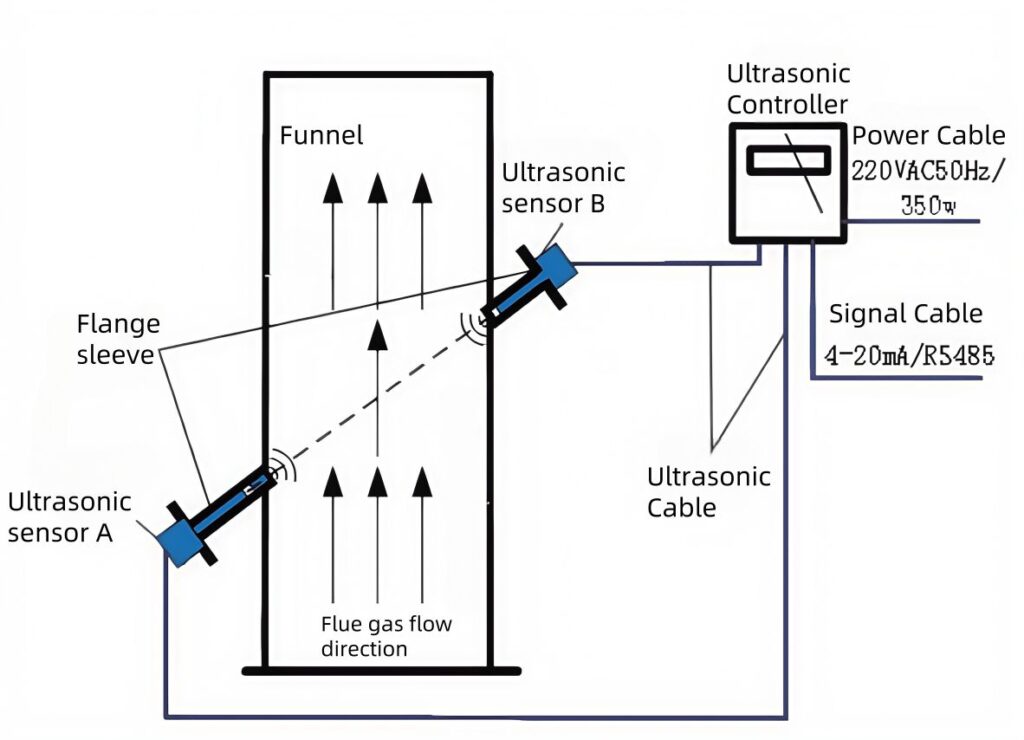
Proper setup of ESEGAS LEUF-200 Ultrasonic Gas Flow Meters for CEMS is crucial for reliable and optimal performance. This guide covers essential aspects of installation. It includes components, installation points, preparation, and instructions.
What Are the Key Components of ESEGAS LEUF-200 Ultrasonic Gas Flow Meters?
Ultrasonic Transducer
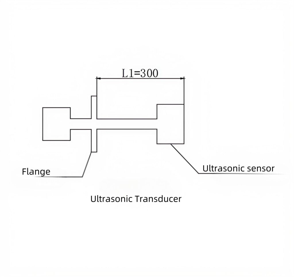
When installing ultrasonic transducers on flue-embedded flanges, critical selection factors require systematic evaluation to ensure optimal probe performance:
Firstly, verify the gas temperature range within operational limits.
Subsequently, analyze gas composition characteristics – specifically identifying whether it’s corrosive, mildly corrosive, or non-corrosive. Additionally, assess flue-specific parameters including diameter dimensions, dust concentration levels, temperature fluctuations, and gas component types/concentrations.
Wall thickness measurement proves essential for proper transducer integration, as inadequate penetration depth compromises measurement accuracy. Finally, confirm the system maintains internal pressure below +5000 Pa, exceeding this threshold risks sensor damage and data distortion.
Through comprehensive evaluation of these interdependent factors – thermal conditions, material compatibility, structural specifications, and pressure constraints – engineers can select transducers ensuring reliable emission monitoring and extended service life in demanding flue environments.
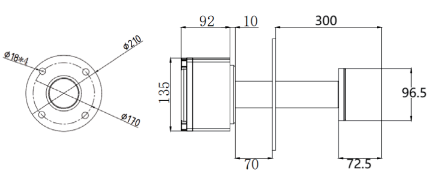
Flange Sleeve
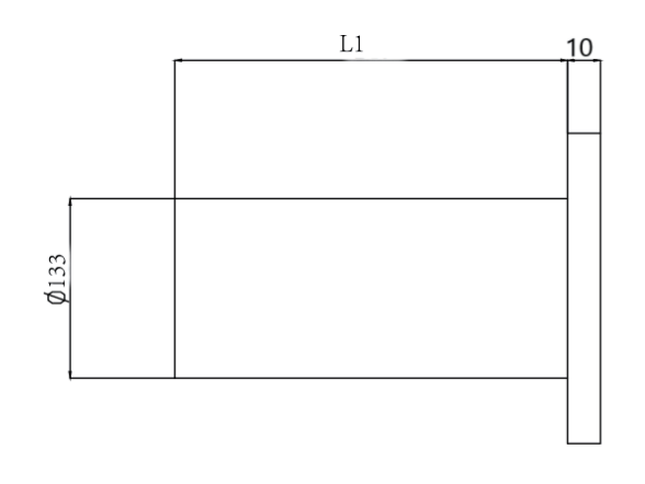
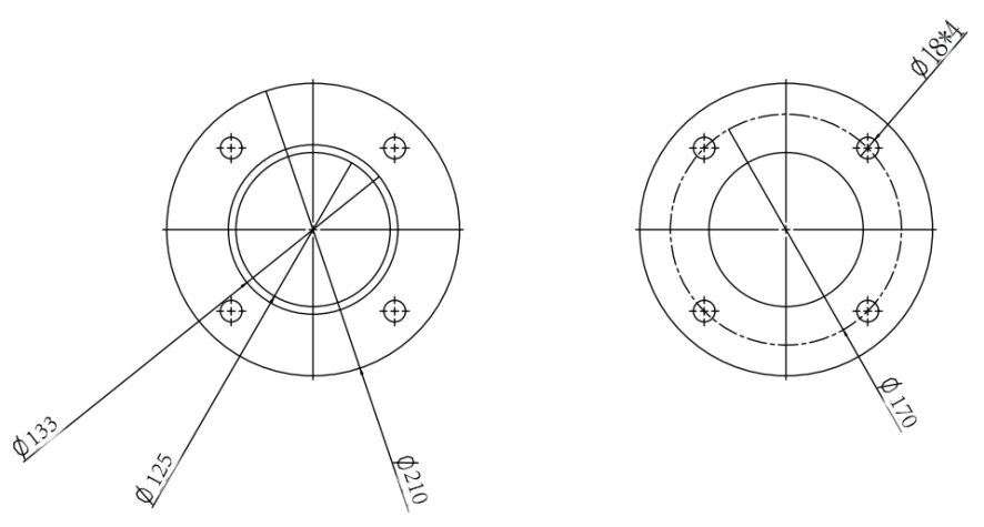
The proper selection of the flange sleeve is critical for ensuring accurate ultrasonic transducer installation. The L1 dimension is primarily determined by the transducer’s installation angle and the wall thickness at the 210 mm flange connection point. This length must precisely accommodate both the mounting geometry and material characteristics of the flue structure.
Material compatibility represents another essential consideration, as the flange and sleeve components must match the specific flue wall construction type. For instance, different material grades are required when interfacing with brick linings versus stainless steel or fiberglass surfaces. This material selection directly impacts both installation stability and long-term measurement reliability.
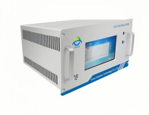
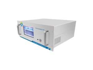
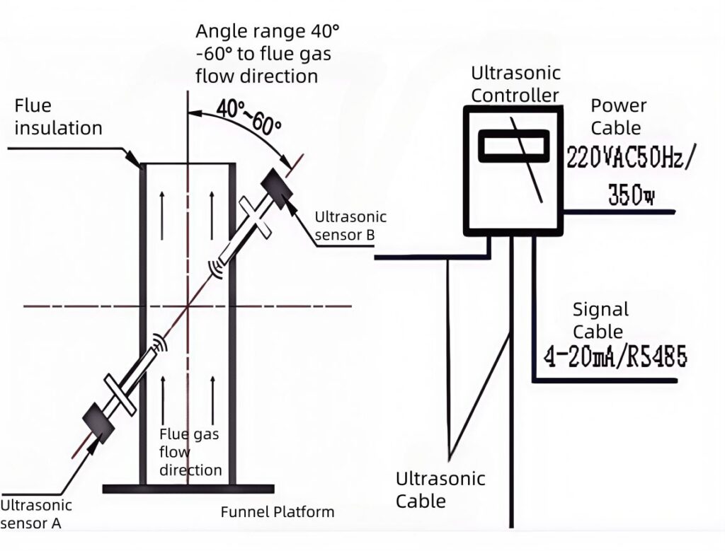
Ultrasonic Controller
The ultrasonic controller incorporates an intuitive touchscreen interface for streamlined parameter configuration. This system efficiently coordinates sound wave transmission and reception, processes collected data in real time, and presents measurement results through clear visual displays. Furthermore, it’s equipped with signal input/output ports and versatile communication interfaces, including 4-20mA current loops and RS-485 serial connections. These interfaces ensure seamless integration with industrial networks through standardized Modbus protocols.
Connecting Cable
The 10-meter sensor cable extends from the probe to connect with the controller, maintaining optimal signal integrity across this extended distance. Meanwhile, power transmission and data communication are handled through separate dedicated cables that interface directly with the ultrasonic controller. This segregated wiring configuration ensures minimal electromagnetic interference between the power supply and sensitive measurement signals, while the standardized connection points simplify system integration. The three-cable architecture (sensor/power/signal) provides a reliable physical framework for stable ultrasonic operations in industrial measurement scenarios.
Where Should I Install ESEGAS LEUF-200 Ultrasonic Gas Flow Meters?
First, identify the optimal measurement location by evaluating pipe geometry and flow conditions. Next, configure the system’s basic parameters considering intended application requirements and operational objectives. When selecting the pipe section, prioritize straight segments that eliminate the need for reducers, ensuring minimal flow disturbance.
Subsequently, choose an appropriate ultrasonic transducer that matches the system’s specifications and measurement requirements. For equipment placement, position the ultrasonic controller in an easily accessible location protected from environmental extremes. Finally, designate the calibration hole- position according to industry standards, selecting an accessible yet non-intrusive location that permits verification without compromising structural integrity.
What Preparations Are Needed Before Installation?
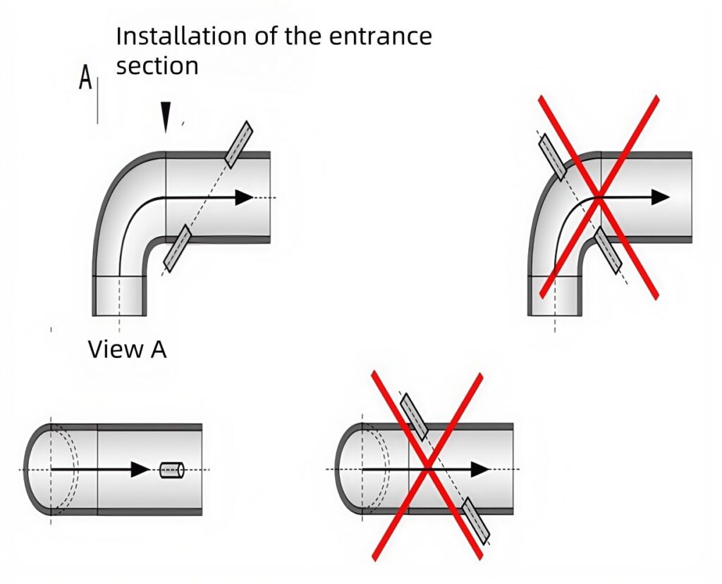
Gas flow dynamics significantly influence measurement accuracy. Specifically, pipe diameter changes and control flap disturbances can create turbulent flow patterns, potentially skewing results by 2-5%. Therefore, strategic positioning becomes critical to minimize measurement deviations.
For optimal performance, install flow meters in straight pipe sections exceeding 10D upstream and 5D downstream (where D=pipe diameter). Ideally, position sensors 30-50 pipe diameters from inlet points to ensure fully developed laminar flow profiles. When retrofitting existing systems, select the most hydraulically stable available location.
Certified technicians should determine LEUF-200 measurement points using computational fluid dynamics simulations, ensuring compliance with ISO 5167 standards for differential pressure devices.
The installation environment must meet two critical criteria: vibration levels below 0.5g RMS (per IEC 60068-2-6) and dedicated power circuits with 500 lux illumination. These provisions enable reliable operation and facilitate routine maintenance access without production interruptions.
How Do I Correctly Install ESEGAS LEUF-200 Ultrasonic Gas Flow Meters?
Generally, there are three primary installation methods for ultrasonic flow meters. Clamp-on Installation: Ensure full liquid-filled pipes before application. Apply acoustic coupled to transducer contact surfaces, and then secure sensors using corrosion-resistant steel straps. This non-invasive method preserves pipe integrity while enabling temporary measurements.
2. Insertion Type Installation: Designed for pipes exceeding 50mm in diameter, this method requires careful spatial planning. Select V or Z mounting configurations depending on spatial constraints. Precise transducer positioning (±1° alignment tolerance) ensures optimal signal transmission across the pipe diameter.
3. Grounding Instructions: Implement dedicated grounding using plated terminal lugs and serrated washers. Connect grounding cables specifically to pipeline flanges, bypassing meter flanges to prevent electrical potential differences. This practice minimizes signal noise interference by 60-80% in field tests.
For ESEGAS LEUF-200 Ultrasonic Gas Flow Meters:
Begin with insertion methodology verification:
– Confirm flange sleeve/probe mechanical integrity
– Validate ultrasonic controller configuration parameters
– Inspect wiring integrity for probes, power (24VDC±10%), and 4-20mA output signals
For >0.7m diameter pipelines:
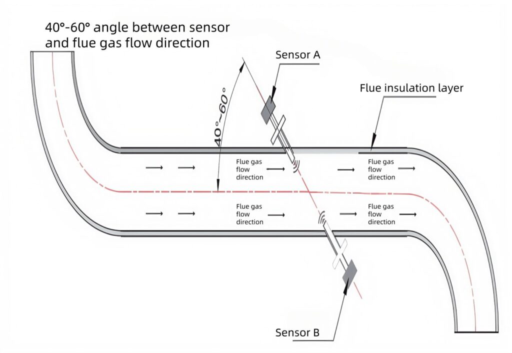
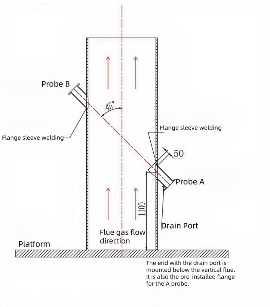
1. Mark installation coordinates using pre-calculated angular positioning (typically 45°-60° relative to flow direction)
2. Remove insulation layers using non-sparking tools
3. Create wall penetrations using diamond-core drills (minimum 125mm diameter)
Installation sequence:
Perform initial spot welding to center-flange the assembly, ensuring <2mm positional deviation. Complete full-perimeter welding after verifying flange perpendicularity (90°±0.5°). Maintain continuous gas purge during welding to prevent particulate ingress. Post-installation, conduct signal strength verification through integrated diagnostic menus.
What Else Should I Consider?
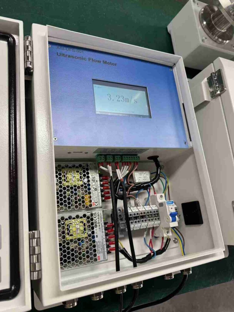
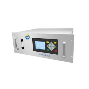
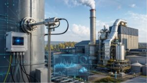
(ESEGAS LEUF-200 Ultrasonic Gas Flow Meters inside)
For proper installation, first, connect all required power and signal cables securely. Always incorporate a power switch and fuse in the circuit for essential safety measures. When implementing air protection devices, consult the [Power Supply] section for specific technical requirements. Use a stable 220VAC 50Hz power source to ensure consistent operation.
Additionally, verifying the installation site provides sufficient electrical capacity and proper illumination. Carefully planning cable routing to maintain adequate slack near transducers, allowing for maintenance adjustments. Finally, protect exposed cable connectors from environmental hazards by using dust covers or moisture-resistant seals.
How to Install LEUF-200 Ultrasonic Transducer?
Begin by carefully removing the protective seal from the flange hole, ensuring no welding slag remains within the flange sleeve. Next, align the ultrasonic sensor probe with the opening and insert it gently, taking care to avoid contact between the probe and the flange sleeve. Secure the assembly by hand-tightening the fasteners until snug, verifying proper alignment throughout the process. Finally, complete the installation by connecting the ultrasonic transducer cable to the controller’s designated interface port, ensuring full compatibility between components.
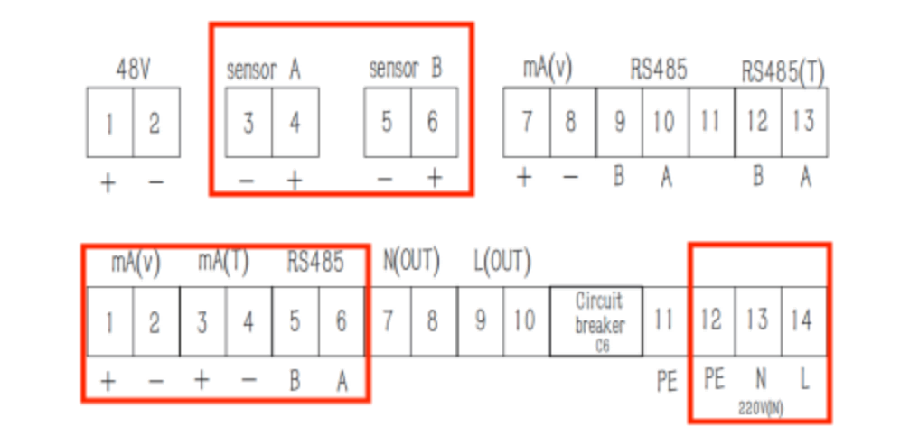
How To Wire the LEUF-200 Ultrasonic Controller
To wire the LEUF-200 ultrasonic controller: First, remove the front panel by carefully unscrewing the four Phillips-head screws. Next, securely connect the specified terminals as outlined in the controller’s wiring diagram, ensuring proper alignment of polarity markers. Finally, route both signal and power cables through the pre-installed cable entry points with locking mechanisms, applying firm pressure until each connector audibly clicks into place. Always verify strain relief engagement before restoring power.
The sensor cable is provided by the manufacturer as standard equipment. Should length adjustments be required, the cable can be extended or shortened accordingly. However, when modifying the cable length, it’s critical to maintain the inter-wire capacitance below 110 pF/m to prevent signal degradation. This capacitance limit applies throughout the entire modified section. Additionally, verify that the conductor diameter consistently meets or exceeds the specified minimum requirements. Both parameters – capacitance control and dimensional compliance – are essential for maintaining signal integrity and ensuring reliable system operation.
If you have any questions, please consult with ESEGAS, please! (https://esegas.com/)
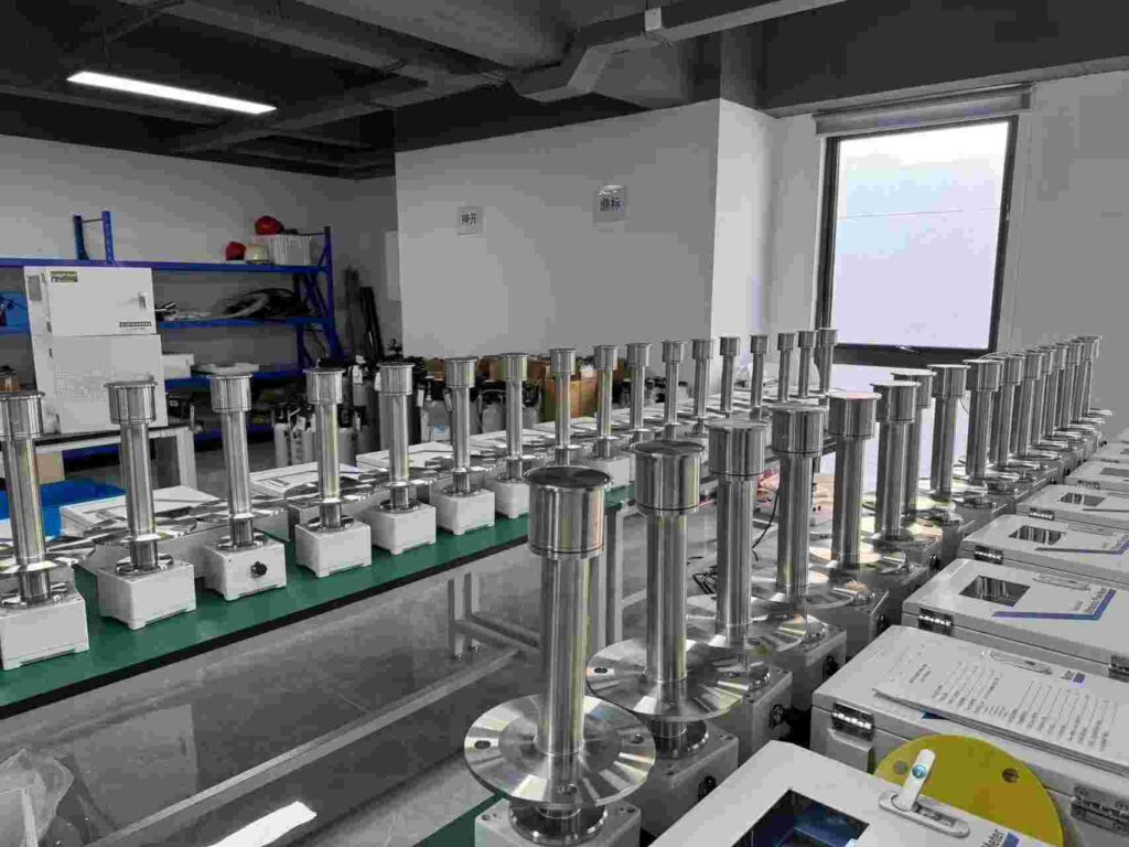
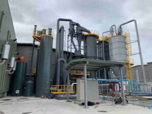
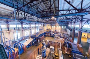
(ESEGAS LEUF-200 Ultrasonic Gas Flow Meters in ESEGAS factory)