Proper maintenance ensures the ESEGAS UV-GAS-500 flue gas analyzer delivers reliable performance and long-term stability. A common issue is optical intensity decay caused by contamination inside the gas chamber. Once the chamber is cleaned, the optical signal typically recovers, and calibration can proceed.
Step 1: Disassembly – Remove Tubes, PT100 Sensor & Chamber Cover
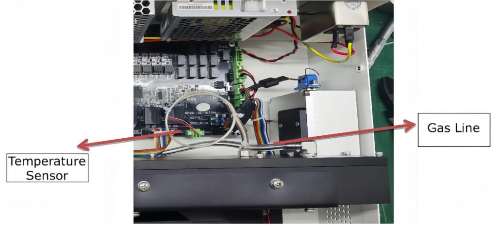
Begin by removing the gas chamber’s inlet and outlet tubes along with the PT100 temperature sensor.
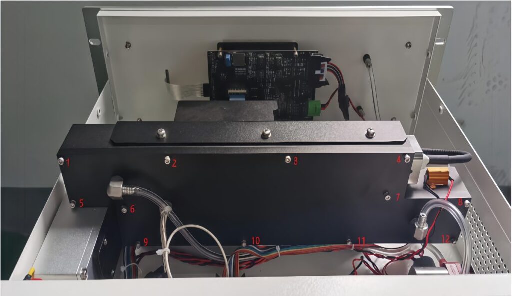
Next, detach the chamber cover and use a 2.5 mm Allen key to unscrew the 12 bolts on the side panel.
Step 2: Cleaning the Gas Chamber – Wipe Lenses, Mirrors & Surfaces
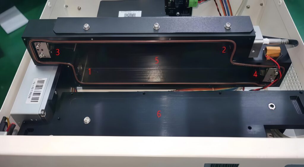
After opening the chamber, identify the optical components. As shown in the diagram, positions 1 and 2 are plano-convex lenses, while positions 3 and 4 are flat mirrors. Use lint-free cloths dipped in alcohol to gently wipe each surface in one direction only. Ensure the bottom (5) and top (6) of the chamber are also cleaned.
Step 3: Energy Check & Zero Calibration – Monitor Spec Curve & Set Zero
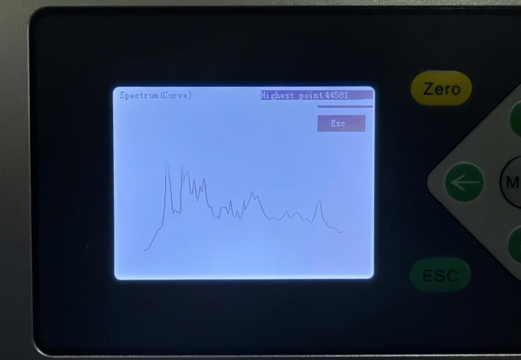
Reassemble the UV-GAS-500 and power on the system. Navigate to the Spec Curve interface—normal energy values should range between 20,000 and 45,000. If the value is below 20,000, additional cleaning of the chamber or fiber optics may be required.
Step 4: Fiber-Optic Endface Cleaning: Restore Signal & Re-test Energy Levels
If energy still fails to meet the threshold—even after correct gas chamber lens cleaning—check the fiber-optic endface:
- Clean it by wiping with dry lens tissue moistened with a little alcohol.
- Wipe in one direction only to prevent damage.
- After cleaning, tighten the fiber head.
- Reinstall the gas chamber module, power up, and allow a 30-minute warm-up. Observe the spectral energy—if it’s now within 20,000–45,000, proceed with zero and span calibration and resume measurement.
- If energy still remains inadequate, replace the fiber optic. After replacement, ensure both ends are tightened and sealed with silicone sealant.
The underlying issue is that contamination in the gas chamber causes signal attenuation, and once properly cleaned, optical strength is restored, allowing accurate calibration.
Step 5: Zero and Span Calibration: Step-by-Step Guide for Accurate NO/NO₂ Measurement
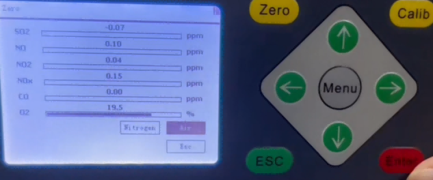
For zero calibration, use either nitrogen or ambient air. In this case, select air as the zero gas and wait for 2-3 minutes. Then , press the Zero button, confirm, and wait until the progress bar completes. Once values stabilize, exit with the ESC key.
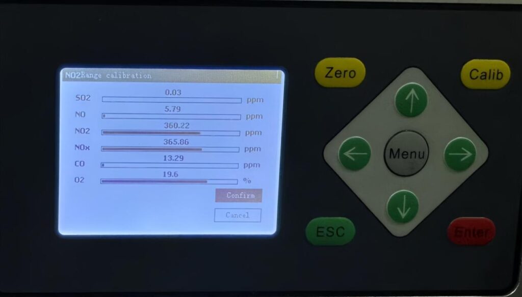
Introduce NO gas and access the NO calibration menu. After wait for 2-3 minutes, press confirm, wait for the process to finish, and exit once values stabilize. Repeat the procedure for NO₂ by entering the NO₂ calibration menu.
This maintenance procedure ensures the UV-GAS-500 flue gas analyzer reliably restores light intensity and accuracy before calibration, facilitating precise flue gas measurements. Ready to perform maintenance on your UV-GAS-500? Following these steps will keep your analyzer in peak condition.
If you want to know more details, visit our YouTube Channel to watch maintenance guide video: https://www.youtube.com/watch?v=cJUDrcXID-A