LSS2004 Dust Concentration Monitor is a new generation product, which can work continuously for a long time in very harsh circumstances, such as in the wind, the rain, the thunder and lightning, the dust, the high temperature and so on. At present it has already been widely applied in the following fields: the particles density test in the fixed source of pollution haze emissions continuous monitoring system (CEMS), the monitoring of filtering equipment efficiency, the monitoring to the combustion efficiency, the measuring to the dust concentration in the industry process of manufacturing, the monitoring to the dust in the Industrial and mining enterprise for health protection, the workshop, the dust load monitoring in the plant, the scientific research, the test in the field, etc., involving the industries including the cement, the thermal power, the iron and steel, the metallurgy, the refinery, the aluminum, the petrochemical, the papermaking, the glass industry, and so on.
LSS2004 is a laser-based backscatter particulate monitor that is designed to measure dust loading of combustion exhaust gas stream. The electrical output from the LSS2004 is proportional to the light scatted back from the particles in the gas stream .The high stable laser signal source projected into the gas flue and those particles can reflect the light whose intensity is proportional to the dust content of the gas stream. The LSS2004 receives the weak laser signal which is reflected by particles, then calculates the concentration of dust by specific algorithm. The instrument is composed by three major parts: the electronic system, the optical system and the mechanical part. The electronic and optical components are protected by mechanical elements. The electronic system uses the digital signal processing technology, which is divided into four parts, including the laser emission module, the optical receiver module, the central process module and the interface module. It uses the advanced digital signal processing techniques and the corresponding embedded software to control system, to realize the functions like the Adaptive Control of light Power, high dynamic range self-adaption lock phase amplification technology, the extremely low zero drifting designing, anti-adverse circumstance, provides fast, reliable and accurate data of the dust discharge. The optical system consists of three parts: light source Po, dust arrester glass G, condensing lens L.
How to change the Dust Monitor LSS2004 Optical Path when you do not know stack diameter ?
A suitable optical path can be obtained by adjusting the angle of the LSD plate where the laser tube is located
■ Tools: Allen wrench, tape measure, etc.
The instrument has 4 PCB boards in total, one is on the top, and the other three are respectively fixed on the upper, lower, left, and right sides of the structure. Find the PCB board where the laser transmitter is located (hereinafter referred to as the LSD board), as shown in Figure 2 below. The dimming range is only related to the LSD board.
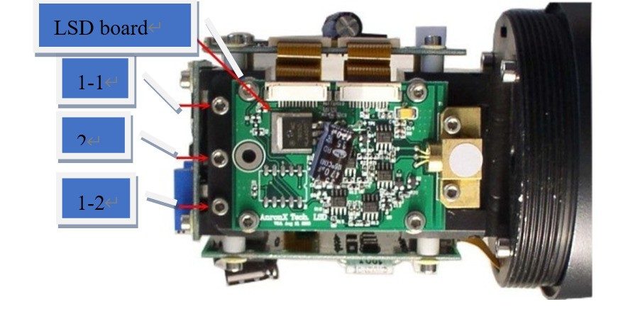
There are three rows of 7 screws on the LSD board. Four of them are used to fix the LSD plate on the bracket to determine whether the laser red spot is on the horizontal axis of the calibration sheet. The dimming range is mainly the three screws on the top of the instrument (1-1, 1-2 and 2 in Figure 2 below), tightening screw 1-1, 1-2 is downward force, tightening screw 2 is upward force Apply force to keep the LSD plate away from the seat.
■ Steps
✔ Make the dust monitor power off and open the back cover of the instrument. Keep the LSD plate on the upper side.
✔ Place the dust monitor flat on a horizontal surface. On the horizontal plane, draw a straight line at the position from the instrument D (the value of the inner diameter of the flue).
✔ After the dust monitor is powered on, observe the position where the red spot of the laser intersects with the horizontal plane. Use the fourth step to make the red spot of the laser intersect with the straight line at D. As shown in Figure 3 below
✔ Reduce the optical pathlength: screw down the screw 2, and loosen the screws 1-1 and 1-2. It will make the tail of the PCB board rise, the emission angle of the light will increase, and the optical path will decrease; otherwise, to increase the optical path: Loosen screw 2, then tighten screws 1-1 and 1-2 down.
✔ Disconnect the power supply, tighten the back cover of the instrument, and the adjustment is completed.✔
■ Testing Method
■ Set an obstacle with an area larger than (160 X 160)mm at the optical path D (similar to the east and west of the flue wall, it is better to be dark), and keep the space around the optical path open, so that the instrument points to the obstacle.
■ After power on, the red spot of the laser should be observed on the obstacle. If not, make sure you are at a distance from instrument D, and pan the obstacle left and right and up and down until you see the light spot. At this time, the output value of the test instrument should approach zero (or 4mA), and it is considered to meet the requirements. Smoke is sprayed at the small D in the optical path, and the recorded data value should change significantly from zero (or 4mA), then it is considered to meet the requirements.
Please contact us if there is any question during the use of the dust monitor