

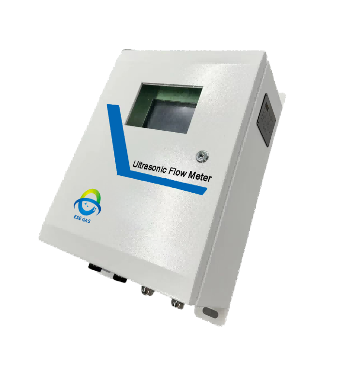
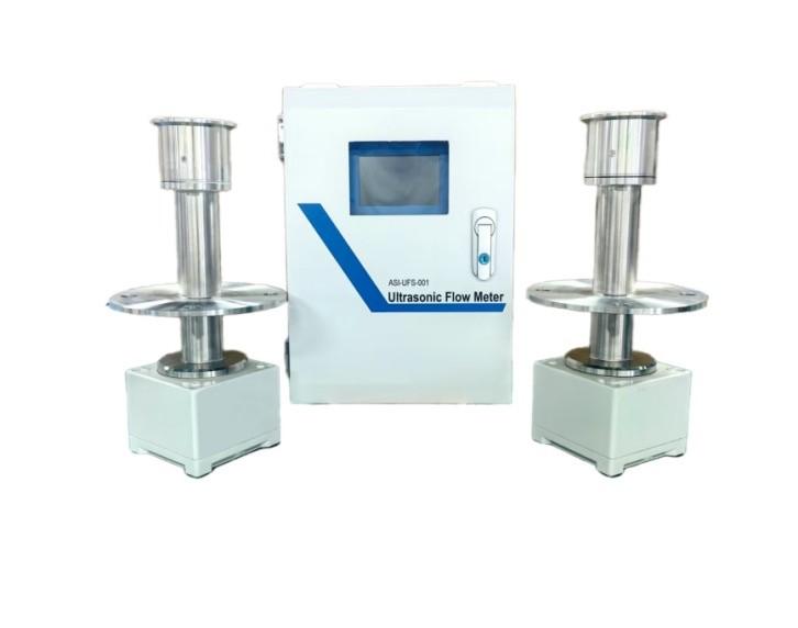
Maintaining ultrasonic gas flow meters is crucial for ensuring accurate measurements and prolonging the lifespan of the equipment. Ultrasonic Flow Meters, which utilize sound waves to measure gas flow without moving parts, require specific attention to detail during both installation and routine maintenance. Below, we explore some essential practices and settings that can help you keep your ESEGAS LEUF-200 ultrasonic gas flow meter in optimal condition.
How does LEUF-200 Ultrasonic Gas Flow Meter Work?
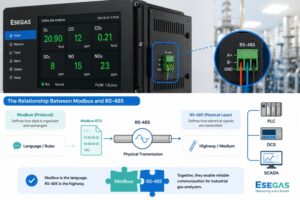
Ultrasonic flow meters operate by sending and receiving ultrasonic pulses through the gas stream. The time it takes for these pulses to travel upstream and downstream is measured, allowing the meter to calculate the flow rate based on the differences in transit time. This technology is not only efficient but also minimizes wear and tear since there are no moving parts involved.
How Do I optimize the settings on ESEGAS LEUF-200 Ultrasonic Gas Flow Meter?
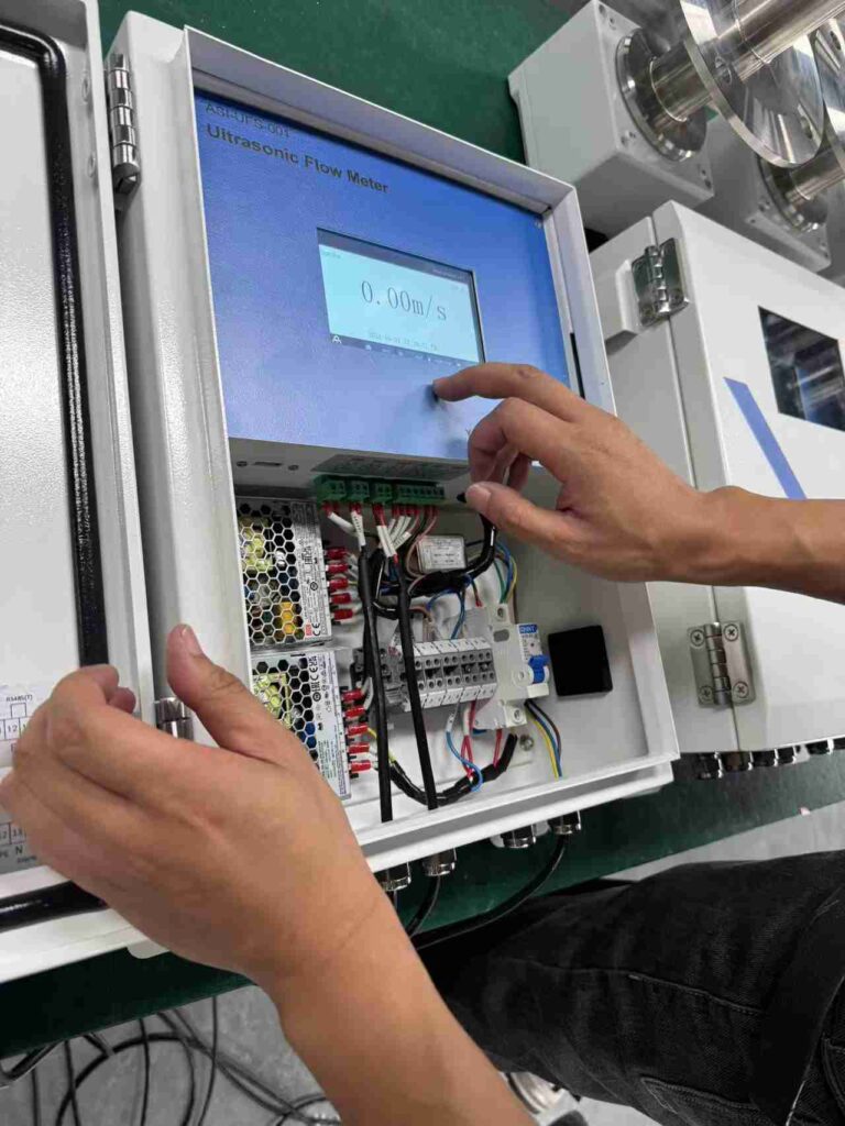
Operators must configure critical on-site parameters, including installation specifications (measuring distance, angle) and output variables. Additionally, if flow velocity measurement axes prove unrepresentative, immediate calibration becomes essential. Let’s examine the operating display interface of LEUF-200 Ultrasonic Gas Flow Meter.
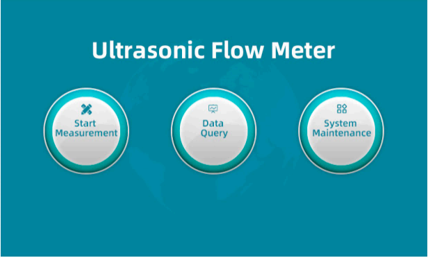
The main interface menu is strategically structured into three core functional modules: Measurement Pages, Data Queries, and System Maintenance.
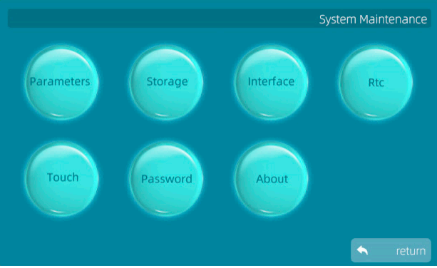
The system maintenance interface provides centralized access to core configuration modules including system parameters, storage settings, and communication interfaces.
Administrators can monitor hardware status through real-time diagnostics while configuring network time protocols and display preferences. For security-sensitive operations, the debugging console remains restricted to authorized users through role-based access controls. Password management features enable periodic credential updates and complexity enforcement, with multi-factor authentication available for enhanced protection. Version control information is systematically organized in the About section, displaying both current firmware iterations and update histories.
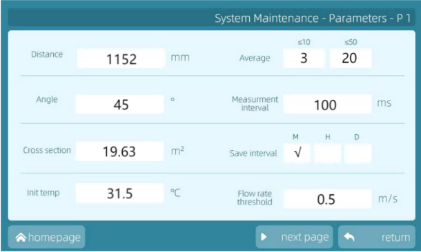
During system maintenance periods, the System Maintenance-Parameters-P1 interface provides a consolidated view of critical operational parameter requiring operator attention.
- Channel Distance: This refers to the actual measured distance between sensor probes, which must align with the effective gas flow measurement distance. The ‘invalid distance’ specifically describes the gap between the flange sleeve and the sensor end face, which exceeds the sleeve length.
- Channel Angle: Parameter represents the angle between the ultrasonic probe tubes and sensors alignment and the gas flow direction. It is crucial to ensure this match the physical installation angle.
- Flue Cross-Section: This setting must correspond to the actual cross-sectional area of the flue at the measurement point for accurate volumetric calculations. Initial Temperature: Defined as the baseline flue gas temperature recorded by measurement instruments prior to system installation.
- Smoothing Times: This parameter determines data stability by averaging multiple measurements. Higher values yield steadier readings but increase response latency. Adjustments should reflect operational requirements. Measurement Interval:Specifies the pause duration between consecutive measurement cycles.
- Flow Rate Saving: Configures data storage frequency (minute/hour/day). No automatic saving occurs if disabled.
- Flow Rate Threshold: When flow rates drop below this preset value, readings default to zero and exclude from cumulative totals. This prevents error accumulation from residual currents during furnace downtime.
To facilitate data portability, a dedicated USB port supports external storage devices for convenient data export in standard formats. Notably, this functionality extends beyond flow metrics—power supply statistics and system logs are also accessible through the interface.
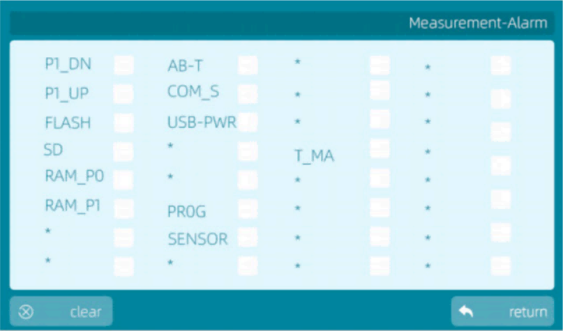
Measurement-Alarm
| P1-DN/UP | Downstream/upstream transducer signal alarm |
| FLASH | FLASH Faulty error report |
| RAM-PO/P1 | Memory fault error report |
| AB-T | Instrument case ambient temperature alarm |
| COM-S | Communication alarm with server |
| USB-PWR | USB power supply fault |
| PROG | Program abnormal error report |
| SENSOR | Transducer abnormal |
| T-MA | Temperature analog output channel abnormal |
Furthermore, discrepancies between factory presets and field applications demand parameter recalibration. Such adjustments typically require manufacturer-engineer intervention to ensure optimal configuration. This protocol maintains measurement integrity while accommodating site-specific operational variables through controlled parameter optimization.
What Routine Inspections Should I Perform?
The LEUF-200 Ultrasonic Gas Flow Meter requires routine maintenance to ensure optimal and sustaining performance. Through scheduled inspection and replacement of consumable components, this practice extends equipment longevity while maintaining measurement accuracy. Notably, the device’s robust design enables quick sub-10-minute maintenance procedures, even under extreme operating conditions. Key tasks include:
– Cleaning ultrasonic transducers and air protection devices
– Replacing instrument air filters
Maintenance Interval
Intervals depend on field operating parameters, including gas composition, temperature, humidity, and environmental factors. While a general 4-week cycle applies to most scenarios, actual intervals should be adjusted based on real-time performance data and site-specific conditions.
Maintenance Commitment
ESEGAS-certified technicians provide tailored maintenance programs aligned with operational requirements. Services follow client-approved schedules with transparent cost structures based on service scope and frequency.
How to Clean the Ultrasonic Transducer?
Regular inspection and cleaning require removing the transducer from its flange.
Required Tools: Spanner; blind flange; screwdriver; brush; clean cloth; alcohol.
Safety First: Always consult the ‘Safety Information’ section before starting. Note that the probe becomes hot during operation – allow it to cool completely before maintenance.
Cleaning Procedure:
1. Begin by wiping the transducer’s white outer surface.
2. Inspect the probe tube and sensor for corrosion, replacing components if necessary.
3. Surface cleaning typically doesn’t require sensor disassembly – focus on removing dust deposits.
4. Ensure debris-free surfaces without damaging the vibrating diaphragm.
Maintenance Intervals:
Depending on operating conditions, schedule cleanings every 2 weeks to 6 months. Monitor component wear closely and replace parts as needed.
Well-executed maintenance not only ensures reliable performance but also directly supports operational efficiency in gas distribution networks.
Ultimately, the whole procedure minimizes downtime risks while maintaining the system’s critical accuracy standards over extended operational periods.
What Are the Common Issues with ESEGAS LEUF-200 Ultrasonic Gas Flow Meters for CEMS?
Even with meticulous implementation, operational challenges may occasionally emerge. Let’s examine practical solutions for common scenarios:
| Symptom | Possible Factors | Troubleshooting Methods |
| No output from the analogue interface | No power supply | Check whether the controller screen is in the running state with the light on |
| Abnormal digital communication | Defective processing board or no connection Faulty cable | Disconnect the main power supply and remove the terminal block to check for abnormalities Check whether the signal cable is short-circuited/open-circuited Circuit board failure Please contactusNote: For safety reasons. |
| Measured values are not refreshed | ldle state | Check whether the measurement status is correct |
| Measured values are not plausible | Incorrect parameter setting | Check whether the main parameters such as distance and angle are set correctly |
| Alarm indication upstream and downstream | Large zero point deviation | Check the zero calibration deviation |
| Signal abnormality | Electronic circuit does not trigger signal to sensorSensor failure Noise | Check the echo on the controller debugging page.Check the appearance of the sensor signal. Contact us |
| Alarm page | Alarm details can be found in the manual under Alarm notes | All line checks |
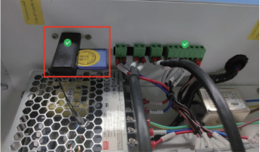
| Fault message The system time cannot be corrected. | The button cell battery at the back of the screen is dead. | If not eliminated, please contact us. Purchase CR2032-3V button battery replacement. |
How to Do On-site Flange Through-Hole and Distance Measurement?
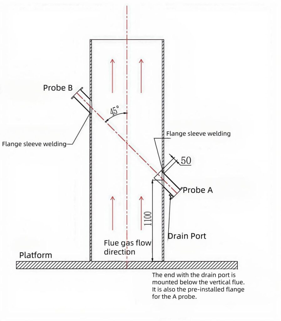
First, reference the diagram to determine probe A’s terminal angle and specified height, then calculate point B’s opening position based on flue diameter measurements. Proceed to drill precisely at both marked locations.
When welding the flange sleeve to probe A’s terminal:
– For angles ≥45°, extend the sleeve’s upper edge 50mm into the flue wall
– For angles <45°, increase penetration to 70mm
Always position the drain outlet directly beneath the sleeve during installation.
Critical requirements:
1. Maintain weld integrity through full circumferential fusion
2. Verify sleeve alignment with calculated coordinates before final welding
3. Implement non-destructive testing to confirm joint reliability
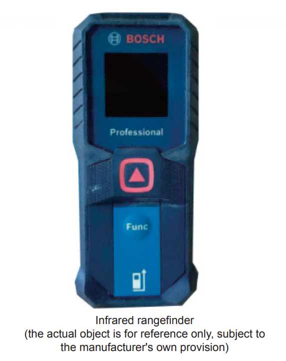
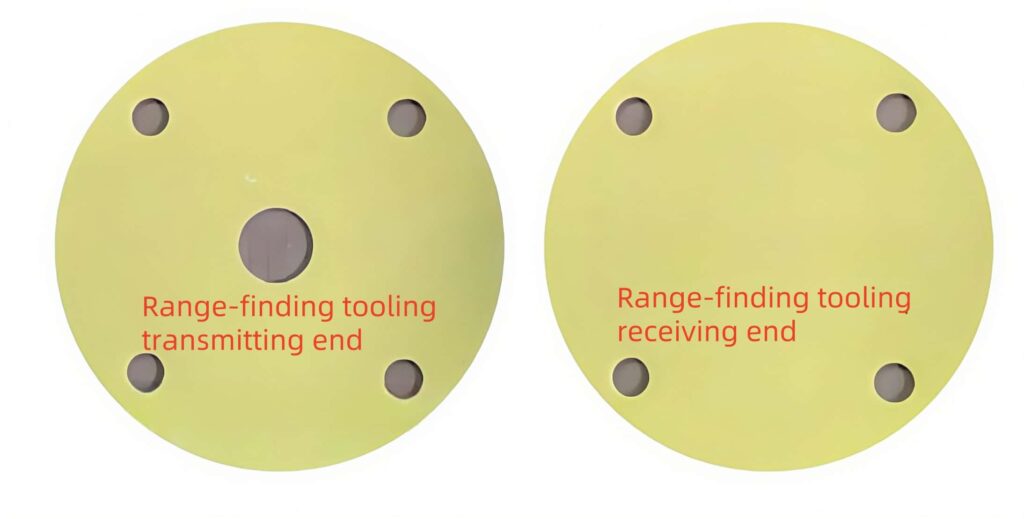
Install the measurement fixture securely using an M16 bolt. After installation, employ an infrared/laser rangefinder to measure the distance between the tool’s transmitting and receiving ends.
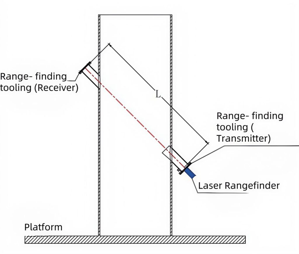
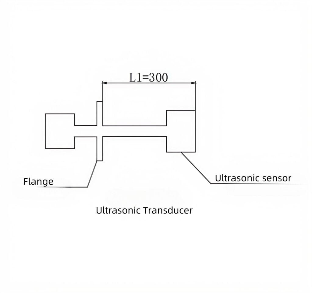
When the rangefinder mark aligns with the receiver, record the measured value as L. Calculate the actual sensor spacing (L_actual) by subtracting the predefined probe-to-flange offsets L1 (design length 300mm per drawing specifications) using the formula: L_actual = L – L1. This calculated value represents the precise installed distance between sensors. Preserve the L_actual measurement for subsequent input into the ultrasonic flow meter’s distance configuration menu via its touch screen interface.
Align the laser rangefinder’s transmitting end with the round hole to emit the measurement beam. Subsequently, observe the receiving end until the reference marking point becomes visible—its color varies depending on the laser rangefinder model. Record the displayed distance data according to your device’s measurement configuration. This value represents the axial separation (L) between the two flange faces on the sleeve assembly.
Critical Note:
Before finalizing measurements, verify whether the instrument’s calibration includes its own physical length. If the displayed value incorporates the device’s dimensions, subtract the rangefinder’s body length from the recorded measurement to obtain the true flange-to-flange distance.
If you want to know more details, contact with us, please!